To use all functions of this page, please activate cookies in your browser.
My watch list
my.chemeurope.com
my.chemeurope.com
With an accout for my.chemeurope.com you can always see everything at a glance – and you can configure your own website and individual newsletter.
- My watch list
- My saved searches
- My saved topics
- My newsletter
Fresnel zoneIn optics and radio communications, a Fresnel zone (pronounced FRA-nel Zone), named for physicist Augustin-Jean Fresnel, is one of a (theoretically infinite) number of concentric ellipsoids of revolution which define volumes in the radiation pattern of a (usually) circular aperture. Fresnel zones result from diffraction by the circular aperture.[1] The cross section of the first Fresnel zone is circular. Subsequent Fresnel zones are annular in cross section, and concentric with the first. To maximize receiver strength, one needs to minimize the effect of the out of phase signals by removing obstacles from the RF Line of Sight (RF LoS). The strongest signals are on the direct line between transmitter and receiver and always lie in the 1st Fresnel Zone. Additional recommended knowledge
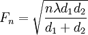
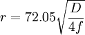
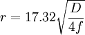
Fresnel zonesIf unobstructed, radio waves will travel in a straight line from the transmitter to the receiver. But if there are obstacles near the path, the radio waves reflecting off those objects may arrive out of phase with the signals that travel directly and reduce the power of the received signal. On the other hand, the reflection can enhance the power of the received signal if the reflection and the direct signals arrive in phase. Sometimes this results in the counterintuitive finding that reducing the height of an antenna increases the S+N/N ratio. Fresnel provided a means to calculate where the zones are where obstacles will cause mostly in phase and mostly out of phase reflections between the transmitter and the receiver. Obstacles in the first Fresnel will create signals that will be 0 to 90 degrees out of phase, in the second zone they will be 90 to 270 degrees out of phase, in third zone, they will be 270 to 450 degrees out of phase and so on. Odd numbered zones are constructive and even numbered zones are destructive.[2] Determining Fresnel zone clearanceThe concept of Fresnel zone clearance may be used to analyze interference by obstacles near the path of a radio beam. The first zone must be kept largely free from obstructions to avoid interfering with the radio reception. However, some obstruction of the Fresnel zones can often be tolerated, as a rule of thumb the maximum obstruction allowable is 40%, but the recommended obstruction is 20% or less. For establishing Fresnel zones, first determine the RF Line of Sight (RF LoS), which in simple terms is a straight line between the transmitting and receiving antennas. Now the zone surrounding the RF LoS is said to be the Fresnel zone.[3] The general equation for calculating the Fresnel zone radius at any point P in the middle of the link is the following: where, Fn = The nth Fresnel Zone radius in metres d1 = The distance of P from one end in metres d2 = The distance of P from the other end in metres λ = The wavelength of the transmitted signal in metres
where
where
See also
References |
|
| This article is licensed under the GNU Free Documentation License. It uses material from the Wikipedia article "Fresnel_zone". A list of authors is available in Wikipedia. |