To use all functions of this page, please activate cookies in your browser.
My watch list
my.chemeurope.com
my.chemeurope.com
With an accout for my.chemeurope.com you can always see everything at a glance – and you can configure your own website and individual newsletter.
- My watch list
- My saved searches
- My saved topics
- My newsletter
Hydraulic jump
A hydraulic jump is a phenomenon in the science of hydraulics, frequently observed in open channel flow. When liquid at high velocity discharges into a zone of lower velocity, a rather abrupt rise (a step or standing wave) occurs in the liquid surface. The rapidly flowing liquid expands (which in an open channel appears as an increase in elevation), converting some of the initial kinetic energy of flow into a lower kinetic energy, an increased potential energy and the remainder to irreversible losses (turbulence which ultimately converts the energy to heat). The phenomenon is dependent upon the initial fluid speed. If the initial fluid speed is below the critical speed then no jump is possible. For relatively low initial flow speeds above the critical speed an undulating wave appears. As the flow speed increases further the transition grows more abrupt, and at high enough speeds the front will break and curl back upon itself. This rise can be accompanied by violent turbulence, eddying, air entrainment, and surface undulations. Although different terminology has been used historically, two different manifestations of the phenomena are amenable to analysis by the same techniques; hence from the standpoint of the physics involved they are simply variations of one another seen from different frames of reference. Shown in figures in this article, the three different manifestations are:
A related case is a cascade (a wall or undulating wave of water moves downstream overtaking a shallower downstream flow of water as shown in Figure 5 — if considered from a frame of reference which moves with the wave front, this is amenable to the same analysis as a stationary jump) These phenomena are addressed in an extensive literature from a number of technical viewpoints. [1][2][3][4][5][6][7][8][9][10][11][12] [13]
Additional recommended knowledge
Classes of hydraulic jumpsHydraulic jumps can be seen in both a stationary form and a dynamic or moving form. Practically they are subject to explanation using the same analytic approaches, and are simply variants of a single phenomena. Moving hydraulic jumpA tidal bore (or bore) is a hydraulic jump which occurs when the incoming tide forms a wave (or waves) of water that travel up a river or narrow bay against the direction of the current. As is true for hydraulic jumps in general, bores take on various forms depending upon the difference in the waterlevel upstream and down, ranging from an undular wavefront to a shock-wave-like wall of water.[7] Figure 3 shows a tidal bore with the characteristics common to shallow upstream water - a large elevation difference is observed. Figure 4 shows a tidal bore with the characteristics common to deep upstream water - a small elevation difference is observed and the wavefront undulates. In both cases the tidal wave moves at the speed characteristic of waves in water of the depth found immediately behind the wave front. Another variation of the moving hydraulic jump is the cascade. In the cascade (an example of which is found in Figure 5), a series of roll waves or undulating waves of water moves downstream overtaking a shallower downstream flow of water. Stationary hydraulic jumpThe stationary hydraulic jump, most frequently seen on rivers and on engineered features such as outfalls of dams and irrigation works, occurs when a flow of liquid at high velocity discharges into a zone of the river or engineered structure which can only sustain a lower velocity. When this occurs, the water slows in a rather abrupt rise (a step or standing wave) on the liquid surface. Comparing the characteristics before and after, one finds:
Analysis of the hydraulic jump on a liquid surfaceIn spite of the apparent complexity of the flow transition, application of simple analytic tools to a two dimensional analysis were historically effective in providing analytic results which closely paralleled both field and laboratory results. Analyses have
Height of the jumpThere are several methods of predicting the height of a hydraulic jump.[14][1][2][3][4][8][13] They all reach common conclusions that:
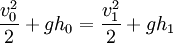
Assuming a two-dimensional situation with flow rate (q) as shown by figure 7 below, the energy principle yield an expression of the energy loss in the hydraulic jump. Indeed hydraulic jumps are commonly used as energy dissipaters downstream of dam spillways ().
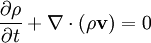
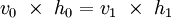
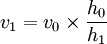
In fluid dynamics, the equation of continuity is effectively an equation of conservation of mass. Considering any fixed closed surface within an incompressible moving fluid, the fluid flows into a given volume at some points and flows out at other points along the surface with no net change in mass within the space since the density is constant. Its differential form the equation of continuity is: where ρ is density, t is time, and v is fluid velocity. Since the density is constant and we are considering only a 2-dimensional case, this integrates to:
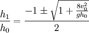
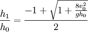
Substituting yields a cubic equation which can be solved using Cardano’s method to determine that: Negative answers do not yield meaningful physical solutions, so this reduces to: This produces three solutions:
Since
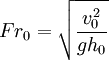
The ratio of the flow height before the jump and after the jump can be simply expressed in terms of the Froude number of the incoming flow. The greater that the flow is supercritical, the more pronounced the jump will be. Practically this means that water accelerated by large drops can create stronger standing waves in the form of hydraulic jumps as it decelerates at the base of the drop. Such standing waves, when found downstream of a weir or natural rock ledge, can form an extremely dangerous "keeper" with a water wall that "keeps" floating objects (e.g., logs, kayaks or kayakers) recirculating in the standing wave for extended periods.
A similar analysis, reaching exactly the same results, derives the same results starting with the impulse-momentum principle. This equation yields the same overall relationship between jump height and Froude number. Energy dissipation by a hydraulic jump
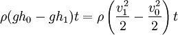
One of the most important engineering applications of the hydraulic jump is to dissipate energy in canals, dam spillways, and similar structures so that the excess kinetic energy does not damage these structures. The energy dissipation or head loss across a hydraulic jump is a function of the magnitude of the jump. The larger the jump as expressed in the fraction of final height to initial height, the greater the head loss. Analytically (using the model developed by R.W. Fox & A.T. McDonald[4]), the fractional energy loss (FEL) can be expressed in terms of the Froude number (Fr0) for the incident flow as: Since
Location of hydraulic jump in a streambed or an engineered structureIn the design of a dam the energy of the fast-flowing stream over a spillway must be partially dissipated to prevent erosion of the streambed downstream, which could ultimately lead to failure of the dam. This can be done by arranging for the formation of an hydraulic jump to dissipate energy. To limit damage, this hydraulic jump normally occurs on an apron engineered to withstand hydraulic forces and to prevent local cavitation and other phenomena which accelerate erosion. In the design of a spillway and apron, the engineers select the point at which a hydraulic jump will occur. Obstructions (such as a lip) or slope changes are routinely designed into the apron to force a jump as a specific location — obstructions are unnecessary as the slope change alone is normally sufficient. To trigger the hydraulic jump without obstacles, an apron is designed such that the flat slope of the apron retards the rapidly flowing water from the face of the dam. If the apron slope is insufficient to maintain the original high velocity, a jump will occur. Two methods of designing an induced jump are common:
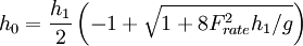
In both cases, the final depth of the water is determined by the downstream characteristics. The jump will occur if and only if the level of inflowing (supercritical) water level (h0) satisfies the condition:
Applying wave theory to the hydraulic jumpIn fluid dynamics, gravity waves are waves generated in a fluid which has as the restoring force, gravity. Gravity waves on an air-water interface are called surface gravity waves or surface waves. Hydraulic jumps, ocean waves and tsunamis can all be treated as examples of gravity waves.[2][7] The wave speed or celerity (speed of individual waves, as opposed to the speed of a group of waves) of gravity waves in shallow water is given by:
In which:
The constraints on the approximation for the speed of a gravity wave as
A hydraulic jump can be viewed as discontinuous waves of all frequencies (wavelengths), which are generated and propagate from a point near the jump. The waves propagate both upstream and downstream. Since a large fraction of the waves fall in a wavelength range where they are shallow water gravity waves that move at the same speed for a given depth, they move upstream at the same rate; however as the water shallows upstream, their speed drops quickly, limiting the rate at which they can propagate upstream to Viewing the hydraulic jump from a wave perspective provides another insight into the phenomena. When the incoming water speed is slow enough, a number of the longer wavelength waves propagate faster than the incoming flow, and can disperse upstream as well as downstream. The deeper the incoming water is the more pronounced the dispersion effect will be. Only a small subset of frequencies (wavelengths) will match the speed of the flow. This truncation of the Fourier spectrum results in a hydraulic jump characterized by undulating waves rather than an abrupt jump. When visible undulations are present, the wavelength of the visible undulations provide a direct indication of the speed of the water upstream of the hydraulic jump. This characteristic behavior allows one to estimate the prejump water depth and water speed simply by observing the height of the jump, the characteristics of the jump, and correlating them as tabulated below. Such an “eyeball” estimate is routinely used by river runners while judging rapids; their conclusions are generally based on an intuitive sense rather than an analytic approach. Tabular summary of the analytic conclusions
NB: the above classification is very rough. Undular hydraulic jumps have been observed with inflow/prejump Froude numbers up to 3.5 to 4[13] . Hydraulic jump variationsAlthough the previous discussion has focused on the straight-forward simple channel approximation, a number of variations are amenable to similar analyses as well. They also serve the important function of allowing the student to perform simple experiments with everyday objects. Shallow fluid hydraulic jumps
Figure 2 above illustrates a daily example of a hydraulic jump can be seen in the sink. Around the place where the tap water hits the sink, you will see a smooth looking flow pattern. A little further away, you will see a sudden 'jump' in the water level. This is a hydraulic jump. The nature of this jump differs from those previously discussed in the following ways:
Changes in the behavior of the jump can be observed by changing the flow rate. Internal wave hydraulic jumpsHydraulic jumps in abyssal fan formationTurbidity currents can result in internal hydraulic jumps (i.e., hydraulic jumps as internal waves in fluids of different density) in abyssal fan formation. The internal hydraulic jumps have been associated with salinity or temperature induced stratification as well as with density differences due to suspended materials. When the bed slope over which the turbidity current flattens, the slower rate of flow is mirrored by increased sediment deposition below the flow, producing a gradual backward slope (i.e., a slope which rises against the current). Where a hydraulic jump occurs, the signature is an abrupt backward slope, corresponding to the rapid reduction in the flow rate at the point of the jump.[16] Atmospheric hydraulic jumpsIndustrial and recreational applications for hydraulic jumps
IndustrialThe hydraulic jump is the most commonly used choice of design engineers for energy dissipation below spillways and outlets. A properly designed hydraulic jump can provide for 60-70% energy dissipation of the energy in the basin itself, limiting the damage to structures and the streambed. Even with such efficient energy dissipation, stilling basins must be carefully designed to avoid serious damage due to uplift, vibration, cavitation, and abrasion. An extensive literature has been developed for this type of engineering.[5][6][11] RecreationalWhile travelling down river, kayaking and canoeing paddlers will often stop and playboat in standing waves and hydraulic jumps. The standing waves and shock fronts of hydraulic jumps make for popular locations for such recreation. Similarly, kayakers and surfers have been known to ride bores up rivers. See also
References and notes
External links
|
|||||||||||||||||||||||||||||||||||||||||
| This article is licensed under the GNU Free Documentation License. It uses material from the Wikipedia article "Hydraulic_jump". A list of authors is available in Wikipedia. |


 , then
  (i.e., there is no jump)
 , then
  (i.e., there is a negative jump - this can be shown as not conserving energy and is only physically possible if some force were to accelerate the fluid at that point)
 or
or  , then
  (i.e., there is a positive jump)
 , where
  is the
  . Since the
  is the speed of a shallow
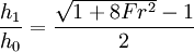

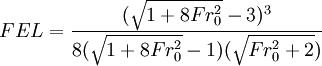
 this is equivalent to concluding the energy loss can be predicted by predicting or measuring the speed and depth of the entering water.
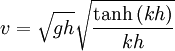 which approaches
  for small h;
 wave number where
  where g is the acceleration of gravity.


