To use all functions of this page, please activate cookies in your browser.
My watch list
my.chemeurope.com
my.chemeurope.com
With an accout for my.chemeurope.com you can always see everything at a glance – and you can configure your own website and individual newsletter.
- My watch list
- My saved searches
- My saved topics
- My newsletter
NanoindentationIndentation tests, sometimes called hardness tests, are perhaps the most commonly applied means of testing the mechanical properties of materials. The technique has its origins in the Mohs scale of mineral hardness, in which materials are ranked according to what they can scratch and are, in turn, scratched by. The characterization of solids in this way takes place on an essentially discrete scale, so much effort has been expended in order to develop techniques for evaluating material hardness over a continuous range. Hence, the adoption of the Meyer, Knoop, Brinell, Rockwell, and Vickers hardness tests. More recently (ca. 1975), the nanoindentation technique has been established as the primary tool for investigating the hardness of small volumes of material. Additional recommended knowledge
BackgroundIn a traditional indentation test (macro or micro indentation), a hard tip whose mechanical properties are known (frequently made of a very hard material like diamond) is pressed into a sample whose properties are unknown. The load placed on the indenter tip is increased as the tip penetrates further into the specimen and soon reaches a user-defined value. At this point, the load may be held constant for a period or removed. The area of the residual indentation in the sample is measured and the hardness, H, is defined as the maximum load, Pmax, divided by the residual indentation area, Ar, or
For most techniques, the projected area may be measured directly using light microscopy. As can be seen from this equation, a given load will make a smaller indent in a "hard" material than a "soft" one. This technique is limited due to large and varied tip shapes, with indenter rigs which do not have very good spatial resolution (the location of the area to be indented is very hard to specify accurately). Comparison across experiments, typically done in different laboratories, is difficult and often meaningless. Nanoindentation improves on these macro and micro indentation tests by indenting on the nanoscale with a very precise tip shape, high spatial resolutions to place the indents, and by providing real-time load-displacement (into the surface) data while the indentation is in progress. Nanoindentation
In nanoindentation small loads and tip sizes are used, so the indentation area may only be a few square micrometres or even nanometres. This presents problems in determining the hardness, as the contact area is not easily found. Atomic force microscopy or scanning electron microscopy techniques may be utilized to image the indentation, but can be quite cumbersome. Instead, an indenter with a geometry known to high precision (usually a Berkovich tip, which has a three-sided pyramid geometry) is employed. During the course of the instrumented indentation process, a record of the depth of penetration is made, and then the area of the indent is determined using the known geometry of the indentation tip. While indenting various parameters, such as load and depth of penetration, can be measured. A record of these values can be plotted on a graph to create a load-displacement curve (such as the one shown in Figure 1). These curves can be used to extract mechanical properties of the material.[1]
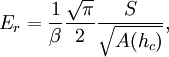
where A(hc) is the area of the indentation at the contact depth hc (the depth of the residual indentation), and β is a geometrical constant on the order of unity. The reduced modulus Er is related to the modulus of elasticity Es of the test specimen through the following relationship from contact mechanics:
Here, the subscript i indicates a property of the indenter material and ν is Poisson's ratio. For a diamond indentor tip, Ei is 1140 GPa and νi is 0.07. Poisson’s ratio varies between 0 and 0.5 for most materials (though it can be negative) and is typically around 0.3.
The hardness is given by the equation above, relating the maximum load to the indentation area. The area can be measured after the indentation by in-situ atomic force microscopy, 'after-the event' optical (or electron) microscopy. An example indent image, from which the area may be determined, is shown at right. Some nanoindenters use an area function based on the geometry of the tip, compensating for elastic load during the test. Use of this area function provides a method of gaining real-time nanohardness values from a load-displacement graph. However, there is some controversy over the use of area functions to estimate the residual areas versus direct measurement. An area function A(h) typically describes the projected area of an indent as a 2nd-order polynomial function of the indenter depth h. Exclusive application of an area function in the absence of adequate knowledge of material response can lead to misinterpretation of resulting data. Cross-checking of areas microscopically is to be encouraged.
where
The subscripts p indicate these values are to be determined from the plastic components only.
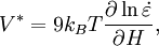
where T is the temperature and kB is Boltzmann's constant. From the definition of m, it is easy to see that DevicesThe construction of a depth-sensing indentation system is made possible by the inclusion of very sensitive displacement and load sensing systems. Load transducers must be capable of measuring forces in the nanonewton range and displacement sensors are very frequently capable of sub-nanometer resolution. Environmental isolation is crucial to the operation of the instrument. Vibrations transmitted to the device, fluctuations in atmospheric temperature and pressure, and thermal fluctuations of the components during the course of an experiment can cause significant errors. LimitationsConventional nanoindentation methods for calculation of Modulus of elasticity (based on the unloading curve) are limited to linear, isotropic materials. Problems associated with the "pile-up" or "sink-in" of the material on the edges of the indent during the indentation process remain a problem that is still under discussion. References
Fischer-Cripps, A.C. Nanoindentation. (Springer: New York), 2004. W.C. Oliver, G.M. Pharr J. Mater. Res. 7 (1992) 1564. Y.-T. Cheng, C.-M. Cheng, Scaling, dimensional analysis, and indentation measurements, Mater. Sci. Eng. R, 44 (2004) 91. J. Malzbender, J.M.J. den Toonder, A.R. Balkenende, G. de With, A Methodology to Determine the Mechanical Properties of Thin Films, with Application to Nano-Particle Filled Methyltrimethoxysilane Sol-Gel Coatings,Mater. Sci. Eng. Reports 36 (2002) 47. Categories: Materials science | Materials testing |
|
| This article is licensed under the GNU Free Documentation License. It uses material from the Wikipedia article "Nanoindentation". A list of authors is available in Wikipedia. |


 .
.


 is the
  is the strain rate produced under the indenter. For nanoindentation experiments which include a holding period at constant load (i.e. the flat, top area of the load-displacement curve),
 .
.


