To use all functions of this page, please activate cookies in your browser.
My watch list
my.chemeurope.com
my.chemeurope.com
With an accout for my.chemeurope.com you can always see everything at a glance – and you can configure your own website and individual newsletter.
- My watch list
- My saved searches
- My saved topics
- My newsletter
Thermoelectric effect
The thermoelectric effect is the direct conversion of temperature differences to electric voltage and vice versa. Simply put, a thermoelectric device creates a voltage when there is a different temperature on each side, and when a voltage is applied to it, it creates a temperature difference. This effect can be used to generate electricity, to measure temperature, to cool objects, or to heat them. Because the direction of heating and cooling is determined by the sign of the applied voltage, thermoelectric devices make very convenient temperature controllers. Traditionally, the term thermoelectric effect or thermoelectricity encompasses three separately identified effects, the Seebeck effect, the Peltier effect, and the Thomson effect. The Peltier and Seebeck effects are the most basic of the three and are essentially the inverses of one another, for which reason the thermoelectric effect may also be called the Peltier–Seebeck effect. This separation derives from the independent discoveries of French physicist Jean Charles Athanase Peltier and Estonian-German physicist Thomas Johann Seebeck. Joule heating, the heat that is generated whenever a voltage is applied to a resistive material, is somewhat related, though it is not generally termed a thermoelectric effect (and it is usually regarded as being a loss mechanism or non-ideality in thermoelectric devices) . The Peltier–Seebeck and Thomson effects are reversible; Joule heating has not been reversed, but is theoretically possible under the laws of thermodynamics. Product highlight
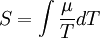
Seebeck effectThe Seebeck effect is the conversion of temperature differences directly into electricity. Seebeck discovered that a compass needle would be deflected when a closed loop was formed of two metals joined in two places with a temperature difference between the junctions. This is because the metals respond differently to the temperature difference, which creates a current loop, which produces a magnetic field. Seebeck, however, at this time did not recognize there was an electric current involved, so he called the phenomenon the thermomagnetic effect, thinking that the two metals became magnetically polarized by the temperature gradient. The Danish physicist Hans Christian Ørsted played a vital role in explaining and conceiving the term "thermoelectricity". The effect is that a voltage, the thermoelectric EMF, is created in the presence of a temperature difference between two different metals or semiconductors. This causes a continuous current to flow in the conductors if they form a complete loop. The voltage created is of the order of several microvolts per degree difference. In the circuit:
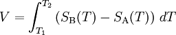
(which can be in several different configurations and be governed by the same equations), the voltage developed can be derived from: SA and SB are the Seebeck coefficients (also called thermoelectric power or thermopower) of the metals A and B as a function of temperature, and T1 and T2 are the temperatures of the two junctions. The Seebeck coefficients are non-linear as a function of temperature, and depend on the conductors' absolute temperature, material, and molecular structure. If the Seebeck coefficients are effectively constant for the measured temperature range, the above formula can be approximated as: The Seebeck effect is commonly used in a device called a thermocouple (because it is made from a coupling or junction of materials, usually metals) to measure a temperature difference directly or to measure an absolute temperature by setting one end to a known temperature. Several thermocouples in connected in series are called a thermopile, which is sometimes constructed in order to increase the output voltage since the voltage induced over each individual couple is small. This is also the principle at work behind thermal diodes and thermoelectric generators (such as radioisotope thermoelectric generators or RTGs) which are used for creating power from heat differentials. The Seebeck effect is due to two effects: charge carrier diffusion and phonon drag. If both connections are held at the same temperature, but one connection is periodically opened and closed, an AC voltage is measured, which is also temperature dependent. This application of the Kelvin probe is sometimes used to argue that the underlying physics does only need one junction. And this effect is still visible if the wires only come close, but do not touch, thus no diffusion is needed. ThermopowerThe thermopower, or thermoelectric power, or Seebeck coefficient of a material is a measure of the magnitude of an induced thermoelectric voltage in response to a temperature difference across that material. The thermopower has units of (V / K), though in practice it is more common to use microvolts per kelvin. Values in the hundreds of μV/K, negative or positive, are typical of good thermoelectric materials. The term thermopower is a misnomer since it measures the voltage or electric field induced in response to a temperature difference, not the electric power. An applied temperature difference causes charged carriers in the material, whether they are electrons or holes, to diffuse from the hot side to the cold side, similar to a classical gas that expands when heated. Mobile charged carriers migrating to the cold side leave behind their oppositely charged and immobile nuclei at the hot side thus giving rise to a thermoelectric voltage (thermoelectric refers to the fact that the voltage is created by a temperature difference). Since a separation of charges also creates an electric potential, the buildup of charged carriers onto the cold side eventually ceases at some maximum value since there exists an equal amount of charged carriers drifting back to the hot side as a result of the electric field at equilibrium. Only an increase in the temperature difference can resume a buildup of more charge carriers on the cold side and thus lead to an increase in the thermoelectric voltage. Incidentally the thermopower also measures the entropy per charge carrier in the material. The thermopower of a material, represented by S (or sometimes by α), depends on the material's temperature and crystal structure. Typically metals have small thermopowers because most have half-filled bands. Electrons (negative charges) and holes (positive charges) both contribute to the induced thermoelectric voltage thus canceling each other's contribution to that voltage and making it small. In contrast, semiconductors can be doped with an excess amount of electrons or holes and thus can have large positive or negative values of the thermopower depending on the charge of the excess carriers. The sign of the thermopower can determine which charged carriers dominate the electric transport in both metals and semiconductors. If the temperature difference ΔT between the two ends of a material is small, then the thermopower of a material is defined as: and a thermoelectric voltage ΔV is seen at the terminals. This can also be written in relation to the electric field E and the temperature gradient In practice one rarely measures the absolute thermopower of the material of interest. This is due to the fact that electrodes attached to a voltmeter must be placed onto the material in order to measure the thermoelectric voltage. The temperature gradient then also typically induces a thermoelectric voltage across one leg of the measurement electrodes. Therefore the measured thermopower includes a contribution from the thermopower of the material of interest and the material of the measurement electrodes. The measured thermopower is then a contribution from both and can be written as: Superconductors have zero thermopower since the charged carriers produce no entropy. This allows a direct measurement of the absolute thermopower of the material of interest, since it is the thermopower of the entire thermocouple as well. In addition, a measurement of the Thompson coefficient, μ, of a material can also yield the thermopower through the relation: The thermopower is an important material parameter that determines the efficiency of a thermoelectric material. A larger induced thermoelectric voltage for a given temperature gradient will lead to a larger efficiency. Ideally one would want very large thermopower values since only a small amount of heat is then necessary to create a large voltage. This voltage can then be used to provide power. Charge carrier diffusionCharge carriers in the materials (electrons in metals, electrons and holes in semiconductors, ions in ionic conductors) will diffuse when one end of a conductor is at a different temperature than the other. Hot carriers diffuse from the hot end to the cold end, since there is a lower density of hot carriers at the cold end of the conductor. Cold carriers diffuse from the cold end to the hot end for the same reason. If the conductor were left to reach thermodynamic equilibrium, this process would result in heat being distributed evenly throughout the conductor (see heat transfer). The movement of heat (in the form of hot charge carriers) from one end to the other is called a heat current. As charge carriers are moving, it is also an electrical current. In a system where both ends are kept at a constant temperature relative to each other (a constant heat current flows from one end to the other), there is a constant diffusion of carriers. If the rate of diffusion of hot and cold carriers in opposite directions were equal, there would be no net change in charge. However, the diffusing charges are scattered by impurities, imperfections, and lattice vibrations (phonons). If the scattering is energy dependent, the hot and cold carriers will diffuse at different rates. This creates a higher density of carriers at one end of the material, and the distance between the positive and negative charges produces a potential difference; an electrostatic voltage. This electric field, however, opposes the uneven scattering of carriers, and an equilibrium is reached where the net number of carriers diffusing in one direction is canceled by the net number of carriers moving in the opposite direction from the electrostatic field. This means the thermopower of a material depends greatly on impurities, imperfections, and structural changes (which often vary themselves with temperature and electric field), and the thermopower of a material is a collection of many different effects. Early thermocouples were metallic, but many more recently developed thermoelectric devices are made from alternating p-type and n-type semiconductor elements connected by metallic interconnects as pictured in the figures below. Semiconductor junctions are especially common in power generation devices, while metallic junctions are more common in temperature measurement. Current flows through the n-type element, crosses a metallic interconnect, and passes into the p-type element. If a power source is provided, the thermoelectric device may act as a cooler, as in the figure to the left below. This is the the Peltier effect, described in the next section. Electrons in the n-type element will move opposite the direction of current flow and holes in the p-type element will move in the direction of current flow, both removing heat from one side of the device. If a heat source is provided, the thermoelectric device may function as a power generator, as in the figure to the right below. The heat source will drive electrons in the n-type element toward the cooler region, thus creating a current through the circuit. Holes in the p-type element will then flow in the direction of the current. The current can then be used to power a load, thus converting the thermal energy into electrical energy.
Phonon dragPhonons are not always in local thermal equilibrium; they move along the thermal gradient. They lose momentum by interacting with electrons (or other carriers) and imperfections in the crystal. If the phonon-electron interaction is predominant, the phonons will tend to push the electrons to one end of the material, losing momentum in the process. This contributes to the already present thermoelectric field. This contribution is most important in the temperature region where phonon-electron scattering is predominant. This happens for where θD is the Debye temperature. At lower temperatures there are fewer phonons available for drag, and at higher temperatures they tend to lose momentum in phonon-phonon scattering instead of phonon-electron scattering. This region of the thermopower-versus-temperature function is highly variable under a magnetic field. Peltier effectThe Peltier effect is the reverse of the Seebeck effect; a creation of a heat difference from an electric voltage. It occurs when a current is passed through two dissimilar metals or semiconductors (n-type and p-type) that are connected to each other at two junctions (Peltier junctions). The current drives a transfer of heat from one junction to the other: one junction cools off while the other heats up; as a result, the effect is often used for thermoelectric cooling. This effect was observed in 1834 by Jean Peltier, 13 years after Seebeck's initial discovery.
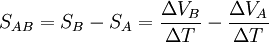
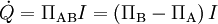
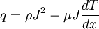
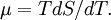
When a current I is made to flow through the circuit, heat is evolved at the upper junction (at T2), and absorbed at the lower junction (at T1). The Peltier heat absorbed by the lower junction per unit time, Where Π is the Peltier coefficient ΠAB of the entire thermocouple, and ΠA and ΠB are the coefficients of each material. P-type silicon typically has a positive Peltier coefficient (though not above ~550 K), and n-type silicon is typically negative, as the names suggest. The Peltier coefficients represent how much heat current is carried per unit charge through a given material. Since charge current must be continuous across a junction, the associated heat flow will develop a discontinuity if ΠA and ΠB are different. This causes a non-zero divergence at the junction and so heat must accumulate or deplete there, depending on the sign of the current. Another way to understand how this effect could cool a junction is to note that when electrons flow from a region of high density to a region of low density, they expand (as with an ideal gas) and cool. The conductors are attempting to return to the electron equilibrium that existed before the current was applied by absorbing energy at one connector and releasing it at the other. The individual couples can be connected in series to enhance the effect. An interesting consequence of this effect is that the direction of heat transfer is controlled by the polarity of the current; reversing the polarity will change the direction of transfer and thus the sign of the heat absorbed/evolved. A Peltier cooler/heater or thermoelectric heat pump is a solid-state active heat pump which transfers heat from one side of the device to the other. Peltier cooling is also called thermo-electric cooling (TEC). Thomson effectThe Thomson effect was predicted and subsequently experimentally observed by William Thomson (Lord Kelvin) in 1851. It describes the heating or cooling of a current-carrying conductor with a temperature gradient. Any current-carrying conductor (except lead), with a temperature difference between two points, will either absorb or emit heat, depending on the material. If a current density J is passed through a homogeneous conductor, heat production per unit volume; where ρ is the resistivity of the material dT/dx is the temperature gradient along the wire μ is the Thomson coefficient. The first term ρ J² is simply the Joule heating, which is not reversible. The second term is the Thomson heat, which changes sign when J changes direction. In metals such as zinc and copper, which have a hotter end at a higher potential and a cooler end at a lower potential, when current moves from the hotter end to the colder end, it is moving from a high to a low potential, so there is an evolution of energy. This is called the positive Thomson effect. In metals such as cobalt, nickel, and iron, which have a cooler end at a higher potential and a hotter end at a lower potential, when current moves from the hotter end to the colder end, it is moving from a low to a high potential, there is an absorption of energy. This is called the negative Thomson effect. In lead, there is zero Thomson effect. The Thomson relationshipsThe Seebeck effect is actually a combination of the Peltier and Thomson effects. In fact, in 1854 Thomson found two relationships, now called the Thomson or Kelvin relationships, between the corresponding coefficients. The absolute temperature T, the Peltier coefficient Π and Seebeck coefficient S are related by the first Thomson relation which predicted the Thomson effect before it was actually formalized. These are related to the Thomson coefficient μ by the second Thomson relation Figure of meritThe figure of merit for thermoelectric devices is defined as
where σ is the electrical conductivity, λ is the thermal conductivity, and S is the Seebeck coefficient or thermopower (conventionally in μV/K). This is more commonly expressed as the dimensionless figure of merit ZT by multiplying it with the average temperature ((T2 + T1) / 2). The value of the figure of merit is usually proportional to the efficiency of the device, subject to certain provisions, particularly the requirement that the two materials of the couple have similar Z values. ZT is therefore a very convenient figure for comparing the potential efficiency of devices using different materials. Values of ZT=1 are considered good, and values of at least the 3–4 range are considered be essential for thermoelectrics to compete with mechanical generation and refrigeration in efficiency. To date, the best reported ZT values have been in the 2–3 range.[1] Much research in thermoelectric materials has focused on increasing the Seebeck coefficient and reducing the thermal conductivity, especially by manipulating the nanostructure of the materials. See also
References
Semiconductors
ERROR 404 Metals
Related
|
|||
| This article is licensed under the GNU Free Documentation License. It uses material from the Wikipedia article "Thermoelectric_effect". A list of authors is available in Wikipedia. |


 , by the equation:


 is equal to

 ,
,
Last viewed


