To use all functions of this page, please activate cookies in your browser.
My watch list
my.chemeurope.com
my.chemeurope.com
With an accout for my.chemeurope.com you can always see everything at a glance – and you can configure your own website and individual newsletter.
- My watch list
- My saved searches
- My saved topics
- My newsletter
Transverse modeA transverse mode of a beam of electromagnetic radiation is a particular intensity pattern of radiation measured in a plane perpendicular (i.e. transverse) to the propagation direction of the beam. Transverse modes occur in radio waves and microwaves confined to a waveguide, and also in light waves in an optical fibre and in a laser's optical resonator. Transverse modes occur because of boundary conditions imposed on the wave by the waveguide. For example, a radio wave in a hollow metal waveguide must have zero electric field amplitude parallel to the walls of the waveguide, and so the transverse pattern of the electric field of waves is restricted to those which fit between the walls. For this reason, the modes supported by a waveguide are quantized. The allowed modes can be found by solving Maxwell's equations for the boundary conditions of a given waveguide.
Product highlight
Types of modesTransverse modes are classified into different types:
Modes of hollow metallic waveguides filled with a homogeneous, isotropic material fall into the first three categories. Otherwise, except in cases of special symmetry, modes are generally of hybrid type. For example, light travelling in an optical fiber or other dielectric waveguide forms hybrid-type modes. The fiber modes are usually referred to as LP (linear polarization) modes, which refers to a scalar approximation for the field solution, treating it as if it contains only one transverse field component (this is accurate because of the low refractive index contrast in typical fibers). A plane light wave propagating through free space is of the transverse electromagnetic (TEM) type and these are also the type of modes generated in a laser's optical resonator. Laser modesIn a laser with cylindrical symmetry, the transverse mode patterns are described by a combination of a Gaussian beam profile with a Laguerre polynomial. The modes are denoted TEMpl where p and l are integers labelling the radial and angular mode orders, respectively. The intensity at a point r,φ (in polar coordinates) from the centre of the mode is given by: where ρ = 2r2/w2, and Lpl is the associate Laguerre polynomial of order p and index l. w is the spot size of the mode corresponding to the Gaussian beam radius. With p=l=0, the TEM00 mode is the lowest order, or fundamental transverse mode of the laser resonator and has the same form as a Gaussian beam. The pattern has a single lobe, and has a constant phase across the mode. Modes with increasing p show concentric rings of intensity, and modes with increasing l show angularly distributed lobes. In general there are 2l(p+1) spots in the mode pattern (except for l=0). The TEM0i* mode, the so-called doughnut mode, is a special case consisting of a superposition of two TEM0i modes (i=1,2,3), rotated 360°/4i with respect to one another. The overall size of the mode is determined by the Gaussian beam radius w, and this may increase or decrease with the propagation of the beam, however the modes preserve their general shape during propagation. Higher order modes are relatively larger compared to the TEM00 mode, and thus the fundamental Gaussian mode of a laser may be selected by placing an appropriately sized aperture in the laser cavity. In many lasers, the symmetry of the optical resonator is restricted by polarizing elements such as Brewster's angle windows. In these lasers, transverse modes with rectangular symmetry are formed. These modes are designated TEMmn with m and n being the horizontal and vertical orders of the pattern. The intensity at point x,y is given by: where Hm(x) is the mth order Hermite polynomial.
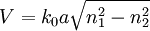
The TEM00 mode corresponds to exactly the same fundamental mode as in the cylindrical geometry. Modes with increasing m and n show lobes appearing in the horizontal and vertical directions, with in general (m+1)(n+1) lobes present in the pattern. As before, higher-order modes have a larger spatial extent than the 00 mode. The phase of each lobe of a TEMmn is offset by π radians with respect to its horizontal or vertical neighbours. This is equivalent to the polarization of each lobe being flipped in direction. The overall intensity profile of a laser's output may be made up from the superposition of any of the allowed transverse modes of the laser's cavity, though often it is desirable to operate only on the fundamental mode. Modes in an optical fiberThe number of modes in an optical fiber distinguishes multi-mode optical fiber from single-mode optical fiber. To determine the number of modes in a step-index fiber, the V number needs to be determined: Decomposition of field distributions into modes is useful because a large number of field amplitudes readings can be simplified into a much smaller number of mode amplitudes. Because these modes change over time according to a simple set of rules, it is also possible to anticipate future behavior of the field distribution. These simplifications of complex field distributions ease the signal processing requirements of fiber-optic communication systems.[2]
See also
|
|
| This article is licensed under the GNU Free Documentation License. It uses material from the Wikipedia article "Transverse_mode". A list of authors is available in Wikipedia. |


![I_{pl} (r,\varphi) = I_0 \rho^l [L_p^l (\rho)]^2 \cos^2 (l\varphi) e^{-\rho}](images/math/f/8/4/f84346eeb598b84fa5de0c3387131fc3.png)
![I_{mn} (x,y) = I_0 \left[ \mbox{H}_m \left( \frac{ \sqrt{2} x}{w} \right) \exp \left( \frac{-x^2}{w^2} \right) \right]^2 \left[ \mbox{H}_n \left( \frac{ \sqrt{2} y}{w} \right) \exp \left( \frac{-y^2}{w^2} \right) \right]^2](images/math/a/e/9/ae992d72f7a373b6ae1c4c593b2ee5bd.png)
 where
where 

