To use all functions of this page, please activate cookies in your browser.
My watch list
my.chemeurope.com
my.chemeurope.com
With an accout for my.chemeurope.com you can always see everything at a glance – and you can configure your own website and individual newsletter.
- My watch list
- My saved searches
- My saved topics
- My newsletter
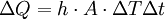
Heat transfer coefficientThe heat transfer coefficient, in thermodynamics and in mechanical and chemical engineering, is used in calculating the heat transfer, typically by convection or phase change between a fluid and a solid: where
From the above equation, the heat transfer coefficient is the proportionality coefficient between the heat flux, Q/(AΔt), and the thermodynamic driving force for the flow of heat (i.e., the temperature difference, ΔT). The heat transfer coefficient has SI units in watts per meter squared-kelvin (W/(m2K)). Heat transfer coefficient can be thought of as an inverse of thermal resistance. There are numerous correlations for calculation of heat transfer coefficient in different heat transfer modes, different fluids, flow regimes, and under different thermohydraulic conditions. Often it can be estimated by dividing the thermal conductivity of the convection fluid by a length scale. The heat transfer coefficient is often calculated from the Nusselt number (a dimensionless number). Product highlight
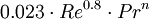
Dittus-Boelter correlationA common and particularly simple correlation useful for many applications is the Dittus-Boelter heat transfer correlation for fluids in turbulent flow. This correlation is applicable when forced convection is the only mode of heat transfer; i.e., there is no boiling, condensation, significant radiation, etc. The accuracy of this correlation is anticipated to be +/-15%. For a liquid flowing in a straight circular pipe with a Reynolds number between 10 000 and 120 000 (in the turbulent pipe flow range), when the liquid's Prandtl number is between 0.7 and 120, for a location far from the pipe entrance (more than 10 pipe diameters; more than 50 diameters according to many authors[1]) or other flow disturbances, and when the pipe surface is hydraulically smooth, it can be expressed as: where
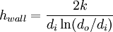
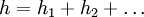
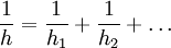
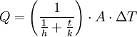
The fluid properties necessary for the application of this equation are evaluated at the bulk temperature thus avoiding iterations. Heat transfer coefficient of pipe wallThe resistance to the flow of heat by the material of pipe wall can be expressed as a "heat transfer coefficient of the pipe wall". However, one needs to select if the heat flux is based on the pipe inner or the outer diameter. Selecting to base the heat flux on the pipe inner diameter, and assuming that the pipe wall thickness is small in comparison with the pipe inner diameter, then the heat transfer coefficient for the pipe wall can be calculated as if the wall were not curved: where k is the effective thermal conductivity of the wall material and t is the wall thickness. If the above assumption does not hold, then the wall heat transfer coefficient can be calculated using the following expression: where di and do are the inner and outer diameters of the pipe, respectively. The thermal conductivity of the tube material usually depends on temperature; the mean thermal conductivity is often used. Combining heat transfer coefficientsFor two or more heat transfer processes acting in parallel, heat transfer coefficients simply add: For two or more heat transfer processes connected in series, heat transfer coefficients add inversely. This means that the overall heat transfer coefficient is a harmonic mean of the partial heat transfer coefficients: For example, consider a pipe with a fluid flowing inside. The rate of heat transfer between the bulk of the fluid inside the pipe and the pipe external surface is: where
ReferencesSee alsoCategories: Heat transfer | Convection |
|
| This article is licensed under the GNU Free Documentation License. It uses material from the Wikipedia article "Heat_transfer_coefficient". A list of authors is available in Wikipedia. |


 => Dittus-Boelter correlation


 =
= 
Last viewed


