To use all functions of this page, please activate cookies in your browser.
My watch list
my.chemeurope.com
my.chemeurope.com
With an accout for my.chemeurope.com you can always see everything at a glance – and you can configure your own website and individual newsletter.
- My watch list
- My saved searches
- My saved topics
- My newsletter
Multipactor effectThe Multipactor effect is a phenomenon in radio frequency (RF) amplifier vacuum tubes and waveguides, where, under certain conditions, secondary electron emission in resonance with an alternating electric field leads to exponential electron multiplication, possibly damaging and even destroying the RF device. Product highlight
DescriptionMultipactor is an effect that occurs when electrons accelerated by radio-frequency (RF) fields are self-sustained in a vacuum (or near vacuum) via an electron avalanche caused by secondary electron emission. The impact of an electron to a surface can, depending on its energy and angle, release one or more secondary electrons into the vacuum. These electrons can then be accelerated by the RF fields and impact with the same or another surface. Should the impact energies, number of electrons released and timing of the impacts be such that a sustained multiplication of the number of electrons occurs, the phenomenon can grow exponentially and may lead to operational problems of the RF system such as damage of RF components or loss/distortion of the RF signal. MechanismThe mechanism of multipactor depends on the orientation of an RF electric field with respect to the surface. There are two types of multipactor: two-surface multipactor on metals and single-surface multipactor on dielectrics. Two-surface multipactor on metalsThis is a multipactor that occurs in the gap between metallic electrodes. Often, an RF electric field is normal to the surface. A resonance between electron flight time and rf field cycle is a mechanism for multipactor development. The existence of multipactor is dependent on the following three conditions being met: The average number of electrons released is greater than or equal to one per incident electron (this is dependent on the secondary electron yield of the surface) and the time taken by the electron to travel from the surface from which it was released to the surface it impacts with is an integer multiple of one half of the RF period and the average secondary electron yield is greater than or equal to one. Single-surface multipactor on dielectricsThis is a multipactor that occurs on a dielectric surface. Often, an RF electric field is parallel to the surface. The positive charge accumulated on the dielectric surface returns electrons back to the surface. Frequency-Gap Product in Two Surface MultipactorThe conditions under which multipactor will occur in two surface multipactor can be described by a quantity called the frequency-gap product. Consider a two surface setup with the following definitions:
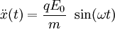
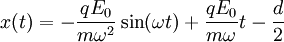
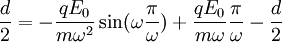
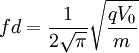
The RF voltage varies sinusoidally. Consider the time at which the voltage at electrode A passes through 0 and starts to become negative. Assuming that there is at least 1 free electron near A, that electron will begin to accelerate to the right toward electrode B. It will continue to accelerate and reach a maximum velocity ½ of a cycle later just as the voltage at electrode B begins to become negative. If the electron(s) from electrode A strike electrode B at this time and produce additional free electrons, these new free electrons will begin to accelerate toward electrode A. The process may then repeat causing multipactor. We now find the relationship between the plate spacing, RF frequency, and RF voltage that causes the strongest multipactor resonance. Consider a point in time at which electrons have just collided with electrode A at position d/2. The electric field is at zero and is beginning to point to the left so that the newly freed electrons are accelerated toward the right. Newton’s equation of motion of the free electrons is The solution to this differential equation is where we’ve assumed that when the electrons initially leave the electrode they have zero velocity. We know that resonance happens if the electrons arrive at the rightmost electrode after one half of the period of the RF field, Rearranging and using the frequency f instead of the angular frequency gives
The product fd is called the frequency-gap product. Keep in mind that this equation is a criterion for greatest amount of resonance, but multipactor can still occur when this equation is not satisfied. HistoryMultipactor was discovered in the 1920s by Philo T. Farnsworth, the inventor of electronic television, who attempted to take advantage of it as an amplifier. More commonly nowadays, it has become an obstacle to be avoided for normal operation of particle accelerators, vacuum electronics, radars, satellite communication devices, and so forth. A novel form of multipactor has been proposed (Kishek, 1998), and subsequently experimentally observed, in which charging of a dielectric surface considerably changes the dynamics of the multipactor discharge. ReferencesMore information on multipactor may be found in:
See also
|
|
| This article is licensed under the GNU Free Documentation License. It uses material from the Wikipedia article "Multipactor_effect". A list of authors is available in Wikipedia. |


 . Plugging this into our solution for
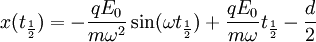
 .
.
Last viewed


