To use all functions of this page, please activate cookies in your browser.
My watch list
my.chemeurope.com
my.chemeurope.com
With an accout for my.chemeurope.com you can always see everything at a glance – and you can configure your own website and individual newsletter.
- My watch list
- My saved searches
- My saved topics
- My newsletter
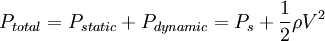
Subsonic and transonic wind tunnelProduct highlight
Subsonic tunnelLow speed wind tunnels are used for operations at very low mach number, with speeds in the test section up to 400 km/h (~ 100 m/s, M = 0.3). They are of open-return type (see figure below), or return flow (see figure below). The air is moved with a propulsion system made of a large axial fan that increases the dynamic pressure to overcome the viscous losses. Open wind tunnel
The working principle is based on the continuity and Bernoulli's equation: The continuity equation is given by:
The Bernoulli equation states:
Putting Bernoulli into the continuity equation gives:
The contraction ratio of a windtunnel can now by calculated by:
Closed wind tunnel
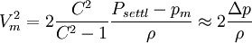
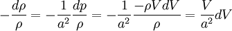
In a return-flow wind tunnel the return duct must be properly designed to reduce the pressure losses and to insure smooth flow in the test section. The compressible flow regime: Again with the continuity law, but now for isentropic flow gives:
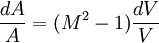
The 1-D area-velocity is known as:
The minimal area A where M=1, also known as the sonic throat area is than given for a perfect gas:
Transonic tunnelHigh subsonic wind tunnels (0.4 < M < 0.75) or transonic wind tunnels (0.75 < M < 1.2) are designed on the same principles as the subsonic wind tunnels. Transonic wind tunnels are able to achieve speeds close to the speeds of sound. The highest speed is reached in the test section. The Mach number is approximately one with combined subsonic and supersonic flow regions. Testing at transonic speeds presents additional problems, mainly due to the reflection of the shock waves from the walls of the test section (see figure below or enlarge the thumb picture at the right). Therefore, perforated or slotted walls are required to reduce shock reflection from the walls. Since important viscous or inviscid interactions occur (such as shock waves or boundary layer interaction) both Mach and Reynolds number are important and must be properly simulated. Large scale facilities and/are pressurized or cryogenic wind tunnels are used.
de Laval nozzle
With a sonic throat, the flow can be accelerated or slowed down. This follows from the 1-D area-Velocity equation. If an acceleration to supersonic flow is required, a convergent-divergent nozzle is required. Otherwise:
Conclusion: The Mach number is controlled by the expansion ratio See also
|
|
| This article is licensed under the GNU Free Documentation License. It uses material from the Wikipedia article "Subsonic_and_transonic_wind_tunnel". A list of authors is available in Wikipedia. |


![\left( \frac{A}{A_{throat}} \right)^2 = \frac{1}{M^2} \left( \frac{2}{\gamma +1} \left( 1 +]] \frac{\gamma -1}{2} M^2 \right) \right)^{\frac{\gamma +1}{\gamma-1}}](images/math/b/0/9/b09725f0649d834adbcac150cd3c1925.png)
 converging

 diverging


