To use all functions of this page, please activate cookies in your browser.
My watch list
my.chemeurope.com
my.chemeurope.com
With an accout for my.chemeurope.com you can always see everything at a glance – and you can configure your own website and individual newsletter.
- My watch list
- My saved searches
- My saved topics
- My newsletter
Bending
In engineering mechanics, bending (also known as flexure) characterizes the behavior of a structural element subjected to an external load applied perpendicular to the axis of the element. A structural element subjected to bending is known as a beam. A closet rod sagging under the weight of clothes on clothes hangers is an example of a beam experiencing bending. Bending produces reactive forces inside a beam as the beam attempts to accommodate the flexural load: in the case of the beam in Figure 1, the material at the top of the beam is being compressed while the material at the bottom is being stretched. There are three notable internal forces caused by lateral loads (shown in Figure 2): shear parallel to the lateral loading, compression along the top of the beam, and tension along the bottom of the beam. These last two forces form a couple or moment as they are equal in magnitude and opposite in direction. This bending moment produces the sagging deformation characteristic of compression members experiencing bending. This stress distribution is dependent on a number of assumptions. First, that 'plane sections remain plane'. In otherwords, any deformation due to shear across the section is not accounted for (no shear deformation). Also, this linear distribution is only applicable if the maximum stress is less than the yield stress of the material. For stresses that exceed yield, refer to article Plastic Bending. The compressive and tensile forces shown in Figure 2 induce stresses on the beam. The maximum compressive stress is found at the uppermost edge of the beam while the maximum tensile stress is located at the lower edge of the beam. Since the stresses between these two opposing maxima vary linearly, there therefore exists a point on the linear path between them where there is no bending stress. The locus of these points is the neutral axis. Because of this area with no stress and the adjacent areas with low stress, using uniform cross section beams in bending is not a particularly efficient means of supporting a load as it does not use the full capacity of the beam until it is on the brink of collapse. Wide-flange beams (I-Beams) and truss girders effectively address this inefficiency as they minimize the amount of material in this under-stressed region. Product highlight
Simple or symmetrical bendingBeam bending is analyzed with the Euler-Bernoulli beam equation. The classic formula for determining the bending stress in a member is: simplified for a beam of rectangular cross-section to:
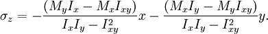
This equation is valid only when the stress at the extreme fiber (i.e. the portion of the beam furthest from the neutral axis) is below the yield stress of the material it is constructed from. At higher loadings the stress distribution becomes non-linear, and ductile materials will eventually enter a plastic hinge state where the magnitude of the stress is equal to the yield stress everywhere in the beam, with a discontinuity at the neutral axis where the stress changes from tensile to compressive. This plastic hinge state is typically used as a limit state in the design of steel structures. Complex or unsymmetrical bendingThe equation above is, also, only valid if the cross-section is symmetrical. For unsymmetrical sections, the full form of the equation must be used (presented below): Complex bending of homogeneous beamsThe complex bending stress equation for elastic, homogeneous beams is given as where Mx and My are the bending moments about the x and y centroid axes, respectively. Ix and Iy are the second moments of area (also known as moments of inertia) about the x and y axes, respectively, and Ixy is the product of inertia. Using this equation it would be possible to calculate the bending stress at any point on the beam cross section regardless of moment orientation or cross-sectional shape. Note that Mx, My, Ix, Iy, and Ixy are all unique for a given section along the length of the beam. In other words, they will not change from one point to another on the cross section. However, the x and y variables shown in the equation correspond to the coordinates of a point on the cross section at which the stress is to be determined. See also
|
|||
| This article is licensed under the GNU Free Documentation License. It uses material from the Wikipedia article "Bending". A list of authors is available in Wikipedia. |