To use all functions of this page, please activate cookies in your browser.
My watch list
my.chemeurope.com
my.chemeurope.com
With an accout for my.chemeurope.com you can always see everything at a glance – and you can configure your own website and individual newsletter.
- My watch list
- My saved searches
- My saved topics
- My newsletter
Yield (engineering)
The yield strength or yield point of a material is defined in engineering and materials science as the stress at which a material begins to deform plastically. Prior to the yield point the material will deform elastically and will return to its original shape when the applied stress is removed. Once the yield point is passed some fraction of the deformation will be permanent and non-reversible. In the three-dimensional space of the principal stresses (σ1,σ2,σ3), an infinite number of yield points form together a yield surface. Knowledge of the yield point is vital when designing a component since it generally represents an upper limit to the load that can be applied. It is also important for the control of many materials production techniques such as forging, rolling, or pressing. In structural engineering, this is a soft failure mode which does not normally cause catastrophic failure unless it accelerates buckling. Product highlight
Definition
It is often difficult to precisely define yielding due to the wide variety of stress–strain curves exhibited by real materials. In addition, there are several possible ways to define yielding[1]:
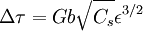
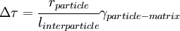
Yield criterionA yield criterion, often expressed as yield surface, or yield locus, is an hypothesis concerning the limit of elasticity under any combination of stresses. There are two interpretations of yield criterion: one is purely mathematical in taking a statistical approach while other models attempt to provide a justification based on established physical principles. Since stress and strain are tensor qualities they can be described on the basis of three principal directions, in the case of stress these are denoted by The following represent the most common yield criterion as applied to an isotropic material (uniform properties in all directions). Other equations have been proposed or are used in specialist situations. Maximum Principal Stress Theory - Yield occurs when the largest principal stress exceeds the uniaxial tensile yield strength. Although this criterion allows for a quick and easy comparison with experimental data it is rarely suitable for design purposes. Maximum Principal Strain Theory - Yield occurs when the maximum principal strain reaches the strain corresponding to the yield point during a simple tensile test. In terms of the principal stresses this is determined by the equation: Maximum Shear Stress Theory - Also known as the Tresca criterion, after the French scientist Henri Tresca. This assumes that yield occurs when the shear stress Total Strain Energy Theory - This theory assumes that the stored energy associated with elastic deformation at the point of yield is independent of the specific stress tensor. Thus yield occurs when the strain energy per unit volume is greater than the strain energy at the elastic limit in simple tension. For a 3-dimensional stress state this is given by: Distortion Energy Theory - This theory proposes that the total strain energy can be separated into two components: the volumetric (hydrostatic) strain energy and the shape (distortion or shear) strain energy. It is proposed that yield occurs when the distortion component exceeds that at the yield point for a simple tensile test. This is generally referred to as the Von Mises criterion and is expressed as: Based on a different theoretical underpinning this expression is also referred to as octahedral shear stress theory. Factors influencing yield stressThe stress at which yield occurs is dependent on both the rate of deformation (strain rate) and, more significantly, the temperature at which the deformation occurs. Early work by Alder and Philips in 1954 found that the relationship between yield stress and strain rate (at constant temperature) was best described by a power law relationship of the form where C is a constant and m is the strain rate sensitivity. The latter generally increases with temperature, and materials where m reaches a value greater than ~0.5 tend to exhibit super plastic behaviour. Later, more complex equations were proposed that simultaneously dealt with both temperature and strain rate: where α and A are constants and Z is the temperature-compensated strain-rate - often described by the Zener-Hollomon parameter: where QHW is the activation energy for hot deformation and T is the absolute temperature. Strengthening MechanismsThere are several ways in which crystalline and amorphous materials can be engineered to increase their yield strength. By altering dislocation density, impurity levels, grain size (in crystalline materials), the yield strength of the material can be fine tuned. This occurs typically by introducing defects such as impurities dislocations in the material. To move this defect (plastically deforming or yielding the material), a larger stress must be applied. This thus causes a higher yield stress in the material. While many material properties depend only on the composition of the bulk material, yield strength is extremely sensitive to the materials processing as well for this reason. These mechanisms for crystalline materials include: 1. Work Hardening - Where machining the material will introduce dislocations, which increases their density in the material. This increases the yield strength of the material, since now more stress must be applied to move these dislocations through a crystal lattice. Dislocations can also interact with each other, becoming entangled. The governing formula for this mechanism is: where σy is the yield stress, G is the shear elastic modulus, b is the magnitude of the Burgers vector, and ρ is the dislocation density. 2. Solid Solution Strengthening - By alloying the material, impurity atoms in low concentrations will occupy a lattice position directly below a dislocation, such as directly below an extra half plane defect. This relieves a tensile strain directly below the dislocation by filling that empty lattice space with the impurity atom. The relationship of this mechanism goes as: where τ is the shear stress, related to the yield stress, G and b are the same as in the above example, C_s is the concentration of solute and ε is the strain induced in the lattice due to adding the impurity. 3. Particle/Precipitate Strengthening - Where the presence of a secondary phase will increase yield strength by blocking the motion of dislocations within the crystal. A line defect that, while moving through the matrix, will be forced against a small particle or precipitate of the material. Dislocations can move through this particle either by shearing the particle, or by a process known as bowing or ringing, in which a new ring of dislocations is created around the particle. The shearing formula goes as:
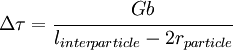
and the bowing/ringing formula:
In these formulas, rparticle is the particle radius, γparticle − matrix is the surface tension between the matrix and the particle, linterparticle is the distance between the particles. 4. Grain boundary strengthening - Where a buildup of dislocations at a grain boundary causes a repulsive force between dislocations. As grain size decreases, the surface area to volume ratio of the grain increases, allowing more buildup of dislocations at the grain edge. Since it requires a lot of energy to move dislocations to another grain, these dislocations build up along the boundary, and increase the yield stress of the material. Also known as Hall-Petch strenghthening, this type of strengthening is governed by the formula: σy = σ0 + kd − 1 / 2 where σ0 is the stress required to move dislocations, k is a material constant, and d is the grain size. Implications for structural engineeringYielded structures have a lower stiffness, leading to increased deflections and decreased buckling strength. The structure will be permanently deformed when the load is removed, and may have residual stresses. Engineering metals display strain hardening, which implies that the yield stress is increased after unloading from a yield state. Highly optimized structures, such as airplane beams and components, rely on yielding as a fail-safe failure mode. No safety factor is therefore needed when comparing limit loads (the highest loads expected during normal operation) to yield criteria.[citation needed] See also
References
Categories: Solid mechanics | Materials science |
||||||||||||||
| This article is licensed under the GNU Free Documentation License. It uses material from the Wikipedia article "Yield_(engineering)". A list of authors is available in Wikipedia. | ||||||||||||||


 ,
,  and
and  .
.

 exceeds the shear yield strength
  :
:

![\frac{1}{2} \Big[ (\sigma_1 - \sigma_2)^2 + (\sigma_2 - \sigma_3)^2 + (\sigma_3 - \sigma_1)^2 \Big] \le \ \sigma_y^2 \,\!](images/math/3/f/3/3f338eef604fb0a07a4a75b7d6894ce9.png)

![\sigma_y = \frac{1}{\alpha} \sinh^{-1} \left [ \frac{Z}{A} \right ]^{(1/n)} \,\!](images/math/3/b/7/3b7fb6d021ba17a9be760dc94880963a.png)
Last viewed


