To use all functions of this page, please activate cookies in your browser.
My watch list
my.chemeurope.com
my.chemeurope.com
With an accout for my.chemeurope.com you can always see everything at a glance – and you can configure your own website and individual newsletter.
- My watch list
- My saved searches
- My saved topics
- My newsletter
Buckling
In engineering, buckling is a failure mode characterized by a sudden failure of a structural member subjected to high compressive stresses, where the actual compressive stresses at failure are smaller than the ultimate compressive stresses that the material is capable of withstanding. This mode of failure is also described as failure due to elastic instability. Mathematical analysis of buckling makes use of an axial load eccentricity that introduces a moment, which does not form part of the primary forces to which the member is subjected. Product highlight
Buckling in columnsThe ratio of the effective length of a column to the least radius of gyration of its cross section is called the slenderness ratio (sometimes expressed with the Greek letter lambda, λ). This ratio affords a means of classifying columns. All the following are approximate values used for convenience.
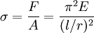
If the load on a column is applied through the center of gravity of its cross section, it is called an axial load. A load at any other point in the cross section is known as an eccentric load. A short column under the action of an axial load will fail by direct compression before it buckles, but a long column loaded in the same manner will fail by buckling (bending), the buckling effect being so large that the effect of the direct load may be neglected. The intermediate-length column will fail by a combination of direct compressive stress and bending. In 1757, mathematician Leonhard Euler derived a formula that gives the maximum axial load that a long, slender, ideal column can carry without buckling. An ideal column is one that is perfectly straight, homogeneous, and free from initial stress. The maximum load, sometimes called the critical load, causes the column to be in a state of unstable equilibrium; that is, any increase in the load, or the introduction of the slightest lateral force, will cause the column to fail by buckling. The Euler formula for columns is where
Examination of this formula reveals the following interesting facts with regard to the load-bearing ability of columns.
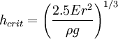
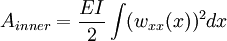
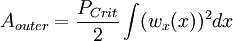
The strength of a column may therefore be increased by distributing the material so as to increase the moment of inertia. This can be done without increasing the weight of the column by distributing the material as far from the principal axes of the cross section as possible, while keeping the material thick enough to prevent local buckling. This bears out the well-known fact that a tubular section is much more efficient than a solid section for column service. Another bit of information that may be gleaned from this equation is the effect of length on critical load. For a given size column, doubling the unsupported length quarters the allowable load. The restraint offered by the end connections of a column also affects the critical load. If the connections are perfectly rigid, the critical load will be four times that for a similar column where there is no resistance to rotation (hinged at the ends). Since the moment of inertia of a surface is its area multiplied by the square of a length called the radius of gyration, the above formula may be rearranged as follows. Using the Euler formula for hinged ends, and substituting A·r2 for I, the following formula results. where F / A is the allowable stress of the column, and l / r is the slenderness ratio. Since the structural column is generally an intermediate-length column and it is impossible to obtain an ideal column, the Euler formula has little practical application for ordinary design. Consequently, a number of empirical column formulae have been developed to agree with test data, all of which embody the slenderness ratio. For design, appropriate safety factors are introduced into these formulae. Self-buckling of columnsA free-standing, vertical column of circular cross-section, with density ρ, Young's modulus E, and radius r, will buckle under its own weight if its height exceeds a certain critical height: Buckling of surface materialsBuckling is also a failure mode in pavement materials, primarily with concrete, since asphalt is more flexible. Radiant heat from the sun is absorbed in the road surface, causing it to expand, forcing adjacent pieces to push against each other. If the stress is great enough, the pavement can lift up and crack without warning. Going over a buckled section can be very jarring to automobile drivers, described as running over a speed hump at highway speeds. Similarly, railroad tracks also expand when heated, and can fail by buckling. It is more common for rails to move laterally, often pulling the underlain railroad ties (sleepers) along with them. Energy methodOften it is very difficult to determine the exact buckling load in complex structures using the Euler formula, due to the difficulty in deciding the constant K. Therefore, maximum buckling load often is approximated using energy conservation. This way of deciding maximum buckling load is often referred to as the energy method in structural analysis. The first step in this method is to suggest a displacement function. This function must satisfy the most important boundary conditions, such as displacement and rotation. The more accurate displacement function, the more accurate result. In this method, there are two equations used to calculate the inner energy and outer energy. where w(x) is the displacement function. Energy conservation yields:
Lateral-torsional bucklingWhen a beam is loaded in flexure, the compression side is in compression, and the tension side is in tension. If the beam is not supported in the lateral direction (i.e., perpendicular to the plane of bending), and the flexural load increases to a critical limit, the beam will fail due to lateral buckling of the compression flange. In wide-flange sections, if the compression flange buckles laterally, the cross section will also twist in torsion, resulting in a failure mode known as lateral-torsional buckling. Plastic bucklingBuckling will generally occur slightly before the theoretical buckling strength of a structure, due to plasticity of the material. When the compressive load is near buckling, the structure will bow significantly and approach yield. The stress-strain behaviour of materials is not strictly linear even below yield, and the modulus of elasticity decreases as stress increases, with more rapid change near yield. This lower rigidity reduces the buckling strength of the structure and causes premature buckling. This is the opposite effect of the plastic bending in beams, which causes late failure relative to the Euler-Bernoulli beam equation. Dynamic bucklingIf the load on the column is applied suddenly and then released, the column can sustain a load much higher than its static (slowly applied) buckling load. This can happen in a long, unsupported column (rod) used as a drop hammer. The duration of compression at the impact end is the time required for a stress wave to travel up the rod to the other (free) end and back down as a relief wave. Maximum buckling occurs near the impact end at a wavelength much shorter than the length of the rod, at a stress many times the buckling stress if the rod were a statically-loaded column. The critical condition for buckling amplitude to remain less than about 25 times the effective rod straightness imperfection at the buckle wavelength is
where σ is the impact stress, L is the length of the rod, c is the elastic wave speed, and h is the smaller lateral dimension of a rectangular rod. Because the buckle wavelength depends only on σ and h, this same formula holds for thin cylindrical shells of thickness h. Source: Lindberg, H. E., and Florence, A. L., Dynamic Pulse Buckling, Martinus Nijhoff Publishers, 1987, pp. 11-56, 297-298. See alsoReferences
Categories: Continuum mechanics | Materials science |
||||||||||||||
| This article is licensed under the GNU Free Documentation License. It uses material from the Wikipedia article "Buckling". A list of authors is available in Wikipedia. | ||||||||||||||