To use all functions of this page, please activate cookies in your browser.
My watch list
my.chemeurope.com
my.chemeurope.com
With an accout for my.chemeurope.com you can always see everything at a glance – and you can configure your own website and individual newsletter.
- My watch list
- My saved searches
- My saved topics
- My newsletter
Cantilever
This is in contrast to a simply supported beam such as those found in a post and lintel system. A simply supported beam is supported at both ends with loads applied between the supports. Product highlight
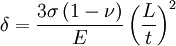
In bridges, towers, and buildingsCantilevers are widely found in construction, notably in cantilever bridges and balconies. In cantilever bridges the cantilevers are usually built as pairs, with each cantilever used to support one end of a central section. The Forth Bridge in Scotland is a famous example of a cantilever truss bridge. Temporary cantilevers are often used in construction. The partially constructed structure creates a cantilever, but the completed structure does not act as a cantilever. This is very helpful when temporary supports, or falsework, cannot be used to support the structure while it is being built (e.g., over a busy roadway or river, or in a deep valley). So some truss arch bridges (see Navajo Bridge) are built from each side as cantilevers until the spans reach each other and are then jacked apart to stress them in compression before final joining. Nearly all cable-stayed bridges are built using cantilevers as this one is one of their chief advantages. Many box girder bridges are built segmentally, or in short pieces. This type of construction lends itself well to balanced cantilever construction where the bridge is built in both directions from a single support. In an architectural application, Frank Lloyd Wright's Fallingwater used cantilevers to project large balconies. The roof built over the stands at Old Trafford Football Ground uses a cantilever so that no supports will block views of the field. Less obvious examples of cantilevers are free-standing radio towers without guy-wires and chimneys, which resist being blown over by the wind through cantilever action at their base. In aircraftAnother use of the cantilever is in fixed-wing aircraft design, pioneered by Hugo Junkers in 1915. Early aircraft wings typically bore their loads by using two (or more) wings in a biplane configuration braced with wires. They were similar to truss bridges, having been developed by Octave Chanute, a railroad bridge engineer. The wings were braced with crossed wires so they would stay parallel, as well as front-to-back to resist twisting. The cables generated considerable drag, and there was constant experimentation on ways to eliminate them. It was also desirable to build a monoplane aircraft, as the airflow around one wing negatively affects the other in a biplane model. Early monoplanes used either struts (as do some current light aircraft), or cables (as do some modern home-built aircraft). The advantage in using struts or cables is a reduction in weight for a given strength, but with the penalty of additional drag. This reduces maximum speed, and increases fuel consumption. The most common current wing design is the cantilever. A single large beam, called the main spar, runs through the wing, typically nearer the leading edge at about 25 percent of the total chord. In flight, the wings generate lift, and the wing spars are designed to carry this load through the fuselage to the other wing. To resist fore and aft movement, the wing will usually be fitted with a second smaller drag-spar nearer the trailing edge, tied to the main spar with structural elements or a stressed skin. The wing must also resist twisting forces, done either by a monocoque "D" tube structure forming the leading edge, or by the aforementioned linking two spars in some form of box beam or lattice girder structure. Cantilever wings require a much heavier spar than would otherwise be needed in cable-stayed designs. However, as the size of an aircraft increases, the additional weight penalty decreases. Eventually a line was crossed in the 1920s, and designs increasingly turned to the cantilever design. By the 1940s almost all larger aircraft used the cantilever exclusively, even on smaller surfaces such as the horizontal stabilizer. In MEMSCantilevered beams are the most ubiquitous structures in the field of microelectromechanical systems (MEMS). MEMS cantilevers are commonly fabricated from Si, SiN or polymers. The fabrication process typically involves undercutting the cantilever structure to release it, often with an anisotropic wet or dry etching technique. Without cantilever transducers, atomic force microscopy would not be possible. A large number of research groups are attempting to develop cantilever arrays as biosensors for medical diagnostic applications. MEMS cantilevers are also finding application as radio frequency filters and resonators. Two equations are key to understanding the behavior of MEMS cantilevers. The first is Stoney's formula, which relates cantilever end deflection δ to applied stress σ:
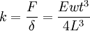
where ν is Poisson's ratio, E is Young's modulus, L is the beam length and t is the cantilever thickness. Very sensitive optical and capacitive methods have been developed to measure changes in the static deflection of cantilever beams used in dc-coupled sensors. The second is the formula relating the cantilever spring constant k to the cantilever dimensions and material constants:
where F is force and w is the cantilever width. The spring constant is related to the cantilever resonance frequency ω0 by the usual harmonic oscillator formula The principal advantage of MEMS cantilevers is their cheapness and ease of fabrication in large arrays. The challenge for their practical application lies in the square and cubic dependences of cantilever performance specifications on dimensions. These superlinear dependences mean that cantilevers are quite sensitive to variation in process parameters. Controlling residual stress can also be difficult. See also
References
|
|
| This article is licensed under the GNU Free Documentation License. It uses material from the Wikipedia article "Cantilever". A list of authors is available in Wikipedia. |


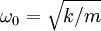 . A change in the force applied to a cantilever can shift the resonance frequency. The frequency shift can be measured with exquisite accuracy using heterodyne techniques and is the basis of ac-coupled cantilever sensors.


