To use all functions of this page, please activate cookies in your browser.
My watch list
my.chemeurope.com
my.chemeurope.com
With an accout for my.chemeurope.com you can always see everything at a glance – and you can configure your own website and individual newsletter.
- My watch list
- My saved searches
- My saved topics
- My newsletter
Optical cavityAn optical cavity or optical resonator is an arrangement of mirrors that forms a standing wave cavity resonator for light waves. Optical cavities are a major component of lasers, surrounding the gain medium and providing feedback of the laser light. They are also used in optical parametric oscillators and some interferometers. Product highlight
Resonator modes
Light confined in a resonator will reflect multiple times from the mirrors, and due to the effects of interference, only certain patterns and frequencies of radiation will be sustained by the resonator, with the others being suppressed by destructive interference. In general, radiation patterns which are reproduced on every round-trip of the light through the resonator are the most stable, and these are the eigenmodes, known as the modes, of the resonator. Resonator modes can be divided into two types: longitudinal modes, which differ in frequency from each other; and transverse modes, which may differ in both frequency and the intensity pattern of the light. The basic, or fundamental transverse mode of a resonator is a Gaussian beam. Resonator typesThe most common types of optical cavities consist of two facing plane (flat) or spherical mirrors. The simplest of these is the plane-parallel or Fabry-Perot cavity, consisting of two opposing flat mirrors. While simple, this arrangement is rarely used in large-scale lasers due the difficulty of alignment; the mirrors must be aligned parallel within a few seconds of arc, or "walkoff" of the intracavity beam will result in it spilling out of the sides of the cavity. However, this problem is much reduced for very short cavities with a small mirror separation distance (L < 1 cm). Plane-parallel resonators are therefore commonly used in microchip and microcavity lasers and semiconductor lasers. In these cases, rather than using separate mirrors, a reflective optical coating may be directly applied to the laser medium itself. The plane-parallel resonator is also the basis of the Fabry-Perot interferometer. For a resonator with two mirrors with radii of curvature R1 and R2, there are a number of common cavity configurations. If the two curvatures are equal to half the cavity length (R1 = R2 = L / 2), a concentric or spherical resonator results. This type of cavity produces a diffraction-limited beam waist in the centre of the cavity, with large beam diameters at the mirrors, filling the whole mirror aperture. Similar to this is the hemispherical cavity, with one plane mirror and one mirror of curvature equal to the cavity length. A common and important design is the confocal resonator, with equal curvature mirrors equal to the cavity length (R1 = R2 = L). This design produces the smallest possible beam diameter at the cavity mirrors for a given cavity length, and is often used in lasers where the purity of the transverse mode pattern is important. A concave-convex cavity has one convex mirror with a negative radius of curvature. This design produces no intracavity focus of the beam, and is thus useful in very high-power lasers where the intensity of the intracavity light might be damaging to the intracavity medium if brought to a focus. Spherical cavityA transparent dielectric sphere, such as a liquid droplet, also forms an interesting optical cavity. Richard K. Chang et al. have demonstrated, in 1986, lasing by using ethanol microdroplets (20-40 micrometers in radius) doped with rhodamine 6G dye. This type of optical cavity exhibits optical resonances when the size of the sphere or the optical wavelength or the refractive index is varied. The resonance is known as morphology-dependent resonance. Stability
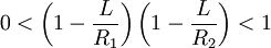
Only certain ranges of values for R1, R2, and L produce stable resonators in which periodic refocussing of the intracavity beam is produced. If the cavity is unstable, the beam size will grow without limit, eventually growing larger than the size of the cavity mirrors and being lost. By using methods such as ray transfer matrix analysis, it is possible to calculate a stability criterion:
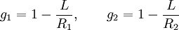
Values which satisfy the inequality correspond to stable resonators. The stability can be shown graphically by defining a stability parameter, g for each mirror:
and plotting g1 against g2 as shown. Areas bounded by the line g1 g2 = 1 and the axes are stable. Cavities at points exactly on the line are marginally stable; small variations in cavity length can cause the resonator to become unstable, and so lasers using these cavities are in practice often operated just inside the stability line. A simple geometric statement describes the regions of stability: A cavity is stable if the line segments between the mirrors and their centers of curvature overlap, but one does not lie entirely within the other. In the confocal cavity a ray, which is deviated from its original direction in the middle between the of the cavity, is maximally (compared to other cavities) displaced on the return to the middle. This prevents amplified spontaneous emission and is important for a good beam quality and high power amplifiers. In wave optics this is expressed by the eigenvalue degeneration of the modes. On every turn to the left, the 0,0 mode and the 1,0 mode are 90° out of phase, but on the turn back, they are 180 °out of phase[citation needed]. Interference of the modes then leads to a displacement. Practical resonatorsIf the optical cavity is not empty (e.g., a laser cavity which contains the gain medium), the value of L used is not the physical mirror separation, but the optical path length between the mirrors. Optical elements such as lenses placed in the cavity alter the stability and mode size. In addition, for most gain media, thermal and other inhomogeneities create a variable lensing effect in the medium, which must be considered in the design of the laser resonator. Practical laser resonators may contain more than two mirrors; three- and four-mirror arrangements are common, producing a "folded cavity". Commonly, a pair of curved mirrors form one or more confocal sections, with the rest of the cavity being quasi-collimated and using plane mirrors. The shape of the laser beam depends on the type of resonator: stable resonators produce a so-called Gaussian beam or a superposition of higher-order Hermite-Gaussian beams. Unstable laser resonators on the other hand, have been shown to produce fractal shaped beams (Link to original article in Nature Vol. 402, 138 (11 November 1999)). Some intracavity elements are usually placed at a beam waist between folded sections. Examples include acousto-optic modulators for cavity dumping and vacuum spatial filters for transverse mode control. For some low power lasers, the laser gain medium itself may be positioned at a beam waist. Other elements, such as filters, prisms and diffraction gratings often need large quasi-collimated beams. These designs allow compensation of the cavity beam's astigmatism, which is produced by Brewster-cut elements in the cavity. A 'Z'-shaped arrangement of the cavity also compensates for coma while the 'delta' or 'X'-shaped cavity does not. Out of plane resonators lead to rotation of the beam profile and more stability. The heat generated in the gain medium leads to frequency drift of the cavity, therefore the frequency can be actively stabilized by locking it to unpowered cavity. Similarly the pointing stability of a laser may still be improved by spatial filtering by an optical fibre. Optical delay linesOptical cavities can also be used as multipass optical delay lines, folding a light beam so that a long path-length may be achieved in a small space. A plane-parallel cavity with flat mirrors produces a flat zigzag light path, but as discussed above, these designs are very sensitive to mechanical disturbances and walk-off. When curved mirrors are used in a nearly confocal configuration, the beam travels on a circular zigzag path. The latter is called a Herriott-type delay line. A fixed insertion mirror is placed off-axis near one of the curved mirrors, and a mobile pickup mirror is similarly placed near the other curved mirror. A flat linear stage with one pickup mirror is used in case of flat mirrors and a rotational stage with two mirrors is used for the Herriott-type delay line. The rotation of the beam inside the cavity alters the polarization state of the beam. To compensate for this, a single pass delay line is also needed, made of either a three or two mirrors in a 3d respective 2d retro-reflection configuration on top of a linear stage. To adjust for beam divergence a second car on the linear stage with two lenses can be used. The two lenses act as a telescope producing a flat phase front of a Gaussian beam on a virtual end mirror. See also
References
|
|
| This article is licensed under the GNU Free Documentation License. It uses material from the Wikipedia article "Optical_cavity". A list of authors is available in Wikipedia. |


 .
.
 ,
,


