To use all functions of this page, please activate cookies in your browser.
My watch list
my.chemeurope.com
my.chemeurope.com
With an accout for my.chemeurope.com you can always see everything at a glance – and you can configure your own website and individual newsletter.
- My watch list
- My saved searches
- My saved topics
- My newsletter
DiffractionDiffraction refers to various phenomena associated with the bending of waves when they interact with obstacles in their path. It occurs with any type of wave, including sound waves, water waves, and electromagnetic waves such as visible light, x-rays and radio waves. As physical objects have wave-like properties, diffraction also occurs with matter and can be studied according to the principles of quantum mechanics. While diffraction always occurs when propagating waves encounter obstacles in their paths, its effects are generally most pronounced for waves where the wavelength is on the order of the size of the diffracting objects. The complex patterns resulting from the intensity of a diffracted wave are a result of interference between different parts of a wave that traveled to the observer by different paths. Product highlight
Examples of diffraction in everyday lifeThe effects of diffraction can be readily seen in everyday life. The most colorful examples of diffraction are those involving light; for example, the closely spaced tracks on a CD or DVD act as a diffraction grating to form the familiar rainbow pattern we see when looking at a disk. This principle can be extended to engineer a grating with a structure such that it will produce any diffraction pattern desired; the hologram on a credit card is an example. Diffraction in the atmosphere by small particles can cause a bright ring to be visible around a bright light source like the sun or the moon. A shadow of a solid object, using light from a compact source, shows small fringes near its edges. All these effects are a consequence of the fact that light is a wave. Diffraction can occur with any kind of wave. Ocean waves diffract around jetties and other obstacles. Sound waves can diffract around objects, this is the reason we can still hear someone calling us even if we are hiding behind a tree. Diffraction can also be a concern in some technical applications; it sets a fundamental limit to the resolution of a camera, telescope, or microscope. History
The effects of diffraction of light were first carefully observed and characterized by Francesco Maria Grimaldi, who also coined the term diffraction, from the Latin diffringere, 'to break into pieces', referring to light breaking up into different directions. The results of Grimaldi's observations were published posthumously in 1665.[2][3] Isaac Newton studied these effects and attributed them to inflexion of light rays. James Gregory (1638–1675) observed the diffraction patterns caused by a bird feather, which was effectively the first diffraction grating. In 1803 Thomas Young did his famous experiment observing diffraction from two closely spaced slits. Explaining his results by interference of the waves emanating from the two different slits, he deduced that light must propagate as waves. Augustin-Jean Fresnel did more definitive studies and calculations of diffraction, published in 1815 and 1818, and thereby gave great support to the wave theory of light that had been advanced by Christiaan Huygens and reinvigorated by Young, against Newton's particle theory. The mechanism of diffractionThe very heart of the explanation of all diffraction phenomena is interference. When two waves combine, their displacements add, causing either a lesser or greater total displacement depending on the phase difference between the two waves. The effect of diffraction from an opaque object can be seen as interference between different parts of the wave beyond the diffraction object. The pattern formed by this interference is dependent on the wavelength of the wave, which for example gives rise to the rainbow pattern on a CD. Most diffraction phenomena can be understood in terms of a few simple concepts that are illustrated below. The most conceptually simple example of diffraction is single-slit diffraction in which the slit is narrow, that is, significantly smaller than a wavelength of the wave. After the wave passes through the slit a pattern of semicircular ripples is formed, as if there were a simple wave source at the position of the slit. This semicircular wave is a diffraction pattern. If we now consider two such narrow apertures, the two radial waves emanating from these apertures can interfere with each other. Consider for example, a water wave incident on a screen with two small openings. The total displacement of the water on the far side of the screen at any point is the sum of the displacements of the individual radial waves at that point. Now there are points in space where the wave emanating from one aperture is always in phase with the other, i.e. they both go up at that point, this is called constructive interference and results in a greater total amplitude. There are also points where one radial wave is out of phase with the other by one half of a wavelength, this would mean that when one is going up, the other is going down, the resulting total amplitude is decreased, this is called destructive interference. The result is that there are regions where there is no wave and other regions where the wave is amplified. Another conceptually simple example is diffraction of a plane wave on a large (compared to the wavelength) plane mirror. The only direction at which all electrons oscillating in the mirror are seen oscillating in phase with each other is the specular (mirror) direction – thus a typical mirror reflects at the angle which is equal to the angle of incidence of the wave. This result is called the law of reflection. Smaller and smaller mirrors diffract light over a progressively larger and larger range of angles. Slits significantly wider than a wavelength will also show diffraction which is most noticeable near their edges. The center part of the wave shows limited effects at short distances, but exhibits a stable diffraction pattern at longer distances. This pattern is most easily understood and calculated as the interference pattern of a large number of simple sources spaced closely and evenly across the width of the slit. This concept is known as the Huygens–Fresnel principle: The propagation of a wave can be visualized by considering every point on a wavefront as a point source for a secondary radial wave. The subsequent propagation and interference of all these radial waves form the new wavefront. This principle mathematically results from interference of waves along all allowed paths between the source and the detection point (that is, all paths except those that are blocked by the diffracting objects). Qualitative observations of diffractionSeveral qualitative observations can be made of diffraction in general:
Quantitative description of diffraction
To determine the pattern produced by diffraction we must determine the phase and amplitude of each of the Huygens wavelets at each point in space. That is, at each point in space, we must determine the distance to each of the simple sources on the incoming wavefront. If the distance to each of the simple sources differs by an integer number of wavelengths, all the wavelets will be in phase, resulting in constructive interference. If the distance to each source is an integer plus one half of a wavelength, there will be complete destructive interference. Usually it is sufficient to determine these minimums and maximums to explain the effects we see in nature. The simplest descriptions of diffraction are those in which the situation can be reduced to a 2 dimensional problem. For water waves, this is already the case, water waves propagate only on the surface of the water. For light, we can often neglect one direction if the diffracting object extends in that direction over a distance far greater than the wavelength. In the case of light shining through small circular holes we will have to take into account the full three dimensional nature of the problem. Diffraction from an array of narrow slits or a grating
Multiple-slit arrangements can be described as multiple simple wave sources, if the slits are narrow enough. For light, a slit is an opening that is infinitely extended in one dimension, which has the effect of reducing a wave problem in 3-space to a simpler problem in 2-space. The simplest case is that of two narrow slits, spaced a distance a apart. To determine the maxima and minima in the amplitude we must determine the difference in path length to the first slit and to the second one. In the Fraunhofer approximation, with the observer far away from the slits, the difference in path length to the two slits can be seen from the image to be Maxima in the intensity occur if this path length difference is an integer number of wavelengths: where:
And the corresponding minima are at path differences of an integer number plus one half of the wavelength: For an array of slits, positions of the minima and maxima are not changed, the fringes visible on a screen however do become sharper as can be seen in the image. The same is true for a surface that is only reflective along a series of parallel lines; such a surface is called a reflection grating. We see from the formula that the diffraction angle is wavelength dependent. This means that different colors of light will diffract in different directions, which allows us to separate light into its different color components. Gratings are used in spectroscopy to determine the properties of atoms and molecules, as well as stars and interstellar dust clouds by studying the spectrum of the light they emit or absorb. Another application of diffraction gratings is to produce a monochromatic light source. This can be done by placing a slit at the angle corresponding to the constructive interference condition for the desired wavelength. Single-slit diffraction
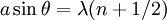
Slits wider than a wavelength will show diffraction at their edges. The pattern is most easily understood and calculated as the interference pattern of a large number of simple sources spaced closely and evenly across the width of the slit. We can determine the minima of the resulting intensity pattern by using the following reasoning. If for a given angle a simple source located at the left edge of the slit interferes destructively with a source located at the middle of the slit, then a simple source just to the right of the left edge will interfere destructively with a simple source located just to the right of the middle. We can continue this reasoning along the entire width of the slit to conclude that the condition for destructive interference for the entire slit is the same as the condition for destructive interference between two narrow slits a distance apart that is half the width of the slit. The result is a formula that looks very similar to the one for diffraction from a grating with the important difference that it now predicts the minima of the intensity pattern.
n is now an integer greater than 0. The same argument does not hold for the maxima. To determine the location of the maxima and the exact intensity profile, a more rigorous treatment is required; a diffraction formalism in terms of integration over all unobstructed paths is required. The intensity profile is then given by
Multiple extended slitsFor an array of slits that are wider than the wavelength of the incident wave, we must take into account interference of wave from different slits as well as interference between waves from different locations in the same slit. Minima in the intensity occur if either the single slit condition or the grating condition for complete destructive interference is met. A rigorous mathematical treatment shows that the resulting intensity pattern is the product of the grating intensity function with the single slit intensity pattern. When doing experiments with gratings that have a slit width being an integer fraction of the grating spacing, this can lead to 'missing' orders. If for example the width of a single slit is half the separation between slits (i.e. the duty cycle of the grating is 50%), the first minimum of the single slit diffraction pattern will line up with the second maximum of the grating diffraction pattern. This expected diffraction peak will then not be visible. The same is true in this case for any even-numbered grating-diffraction peak. Particle diffraction
Quantum theory tells us that every particle exhibits wave properties. In particular, massive particles can interfere and therefore diffract. Diffraction of electrons and neutrons stood as one of the powerful arguments in favor of quantum mechanics. The wavelength associated with a particle is the de Broglie wavelength where h is Planck's constant and p is the momentum of the particle (mass × velocity for slow-moving particles) . For most macroscopic objects, this wavelength is so short that it is not meaningful to assign a wavelength to them. A Sodium atom traveling at about 3000 m/s would have a De Broglie wavelength of about 5 pico meters. Because the wavelength for even the smallest of macroscopic objects is extremely small, diffraction of matter waves is only visible for small particles, like electrons, neutrons, atoms and small molecules. The short wavelength of these matter waves makes them ideally suited to study the atomic crystal structure of solids and large molecules like proteins. Relatively recently, larger molecules like buckyballs,[4] have been shown to diffract. Currently, research is underway into the diffraction of viruses, which, being huge relative to electrons and other more commonly diffracted particles, have tiny wavelengths so must be made to travel very slowly through an extremely narrow slit in order to diffract. Bragg diffraction
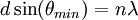
Diffraction from a three dimensional periodic structure such as atoms in a crystal is called Bragg diffraction. It is similar to what occurs when waves are scattered from a diffraction grating. Bragg diffraction is a consequence of interference between waves reflecting from different crystal planes. The condition of constructive interference is given by Bragg's law: where
Bragg diffraction may be carried out using either light of very short wavelength like x-rays or matter waves like neutrons whose wavelength is on the order of the atomic spacing. The pattern produced gives information of the separations of crystallographic planes d, allowing one to deduce the crystal structure. CoherenceThe description of diffraction relies on the interference of waves emanating from the same source taking different paths to the same point on a screen. In this description, the difference in phase between waves that took different paths is only dependent on the effective path length. This does not take into account the fact that waves that arrive at the screen at the same time were emitted by the source at different times. The initial phase with which the source emits waves can change over time in an unpredictable way. This means that waves emitted by the source at times that are too far apart can no longer form a constant interference pattern since the relation between their phases is no longer time independent. The length over which the phase in a beam of light is correlated, is called the coherence length. In order for interference to occur, the path length difference must be smaller than the coherence length. This is sometimes referred to as spectral coherence as it is related to the presence of different frequency components in the wave. In the case light emitted by an atomic transition, the coherence length is related to the lifetime of the excited state from which the atom made its transition. If waves are emitted from an extended source this can lead to incoherence in the transversal direction. When looking at a cross section of a beam of light, the length over which the phase is correlated is called the transverse coherence length. In the case of Young's double slit experiment this would mean that if the transverse coherence length is smaller than the spacing between the two slits the resulting pattern on a screen would look like two single slit diffraction patterns. In the case of particles like electrons, neutrons and atoms, the coherence length is related to the spacial extent of the wave function that describes the particle. Diffraction limit of telescopes
For diffraction through a circular aperture, there is a series of concentric rings surrounding a central Airy disc. The mathematical result is similar to a radially symmetric version of the equation given above in the case of single-slit diffraction. A wave does not have to pass through an aperture to diffract; for example, a beam of light of a finite size also undergoes diffraction and spreads in diameter. This effect limits the minimum diameter d of spot of light formed at the focus of a lens, known as the diffraction limit: where λ is the wavelength of the light, f is the focal length of the lens, and a is the diameter of the beam of light, or (if the beam is filling the lens) the diameter of the lens. The diameter given is enough to contain about 70% of the light energy; it is the radius to the first null of the Airy disk, in approximate agreement with the Rayleigh criterion. Twice that diameter, the diameter to the first null of the Airy disk, within which 83.8% of the light energy is contained, is also sometimes given as the diffraction spot diameter. By use of Huygens' principle, it is possible to compute the far-field diffraction pattern of a wave from any arbitrarily shaped aperture. If the pattern is observed at a sufficient distance from the aperture, or projected onto a screen with a collimating lens, it will appear as the two-dimensional Fourier transform of the function representing the aperture. References
See also
|
||||
| This article is licensed under the GNU Free Documentation License. It uses material from the Wikipedia article "Diffraction". A list of authors is available in Wikipedia. |


![= I_0 {\left[ \operatorname{sinc} \left( \frac{\pi a}{\lambda} \sin \theta \right) \right] }^2](images/math/8/7/9/879714a5b341089490d60a308e259848.png)
![I\left(\theta\right) = I_0 \left[ \operatorname{sinc} \left( \frac{\pi a}{\lambda} \sin \theta \right) \right]^2 \cdot \left[\frac{\sin\left(\frac{N\pi d}{\lambda}\sin\theta\right)}{\sin\left(\frac{\pi d}{\lambda}\sin\theta\right)}\right]^2](images/math/4/8/e/48e0da4b6dab4360ab7699312bd07674.png)