To use all functions of this page, please activate cookies in your browser.
My watch list
my.chemeurope.com
my.chemeurope.com
With an accout for my.chemeurope.com you can always see everything at a glance – and you can configure your own website and individual newsletter.
- My watch list
- My saved searches
- My saved topics
- My newsletter
Plug flow reactor modelThe plug flow reactor (PFR) model is used to describe chemical reactions in continuous, flowing systems. The PFR model is used to predict the behaviour of chemical reactors, so that key reactor variables, such as the dimensions of the reactor, can be estimated. PFRs are also sometimes called as Continuous Tubular Reactors (CTRs). Fluid going through a PFR may be modeled as flowing through the reactor as a series of infinitely thin coherent "plugs", each with a uniform composition, traveling in the axial direction of the reactor, with each plug having a different composition from the ones before and after it. The key assumption is that as a plug flows through a PFR, the fluid is perfectly mixed in the radial direction but not in the axial direction (forwards or backwards). Each plug of differential volume is considered as a separate entity, effectively an infinitesimally small batch reactor, limiting to zero volume. As it flows down the tubular PFR, the residence time (τ) of the plug is a function of its position in the reactor. In the ideal PFR, the residence time distribution is therefore a Dirac delta function with a value equal to τ. Product highlight
PFR modellingPFRs are frequently referred to as piston flow reactors, or sometimes as continuous tubular reactors. They are governed by ordinary differential equations, the solution for which can be calculated providing that appropriate boundary conditions are known. The PFR model works well for many fluids: liquids, gases, and slurries. Although turbulent flow and axial diffusion cause a degree of mixing in the axial direction in real reactors, the PFR model is appropriate when these effects are sufficiently small that they can be ignored. In the simplest case of a PFR model, several key assumptions must be made in order to simplify the problem, some of which are outlined below. Note that not all of these assumptions are necessary, however the removal of these assumptions does increase the complexity of the problem. The PFR model can be used to model multiple reactions as well as reactions involving changing temperatures, pressures and densities of the flow. Although these complications are ignored in what follows, they are often relevant to industrial processes. Assumptions:
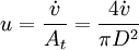
[accumulation] = [in] - [out] + [generation] - [consumption] 1. Fi(x) − Fi(x + dx) + Atdxνir = 0 . [1] When linear velocity, u, and molar flow rate relationships, Fi, 2. When like terms are canceled and the limit dx → 0 is applied to Equation 2 the mass balance on species i becomes 3. where Ci(x) is the molar concentration of species i at position x, At the cross-sectional area of the tubular reactor, dx the differential thickness of fluid plug, and νi stoichiometric coefficient. The reaction rate, r, can be figured by using the Arrhenius temperature dependence. Generally, as the temperature increases so does the rate at which the reaction occurs. Residence time, τ, is the average amount of time a discrete quantity of reagent spends inside the tank. Assume:
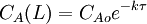
4. where CAo is the inlet concentration of species A. Operation and usesPFRs are used to model the chemical transformation of compounds as they are transported in systems resembling "pipes". The "pipe" can represent a variety of engineered or natural conduits through which liquids or gases flow. (e.g. rivers, pipelines, regions between two mountains, etc.) An ideal plug flow reactor has a fixed residence time: Any fluid (plug) that enters the reactor at time t will exit the reactor at time t + τ, where τ is the residence time of the reactor. The residence time distribution function is therefore a dirac delta function at τ. A real plug flow reactor has a residence time distribution that is a narrow pulse around the mean residence time distribution. A typical plug flow reactor could be a tube packed with some solid material (frequently a catalyst). Sometimes the tube will be a tube in a shell and tube heat exchanger. Advantages and disadvantagesCSTRs and PFRs have fundamentally different equations, so the kinetics of the reaction being undertaken will to some extent determine which system should be used. However there are a few general comments that can be made with regards to PFRs compared to other reactor types. Plug flow reactors have a high volumetric unit conversion, run for long periods of time without maintenance, and the heat transfer rate can be optimized by using more, thinner tubes or less, thicker tubes in parallel. Disadvantages of plug flow reactors are that temperatures are hard to control and can result in undesirable temperature gradients. PFR maintenance is also more expensive than CSTR maintenance. [2] Through a recycle loop a PFR is able to approximate a CSTR in operation. This occurs due to a decrease in the concentration change due to the smaller fraction of the flow determined by the feed; in the limiting case of total recycling, infinite recycle ratio, the PFR perfectly mimics a CSTR. ApplicationsPlug flow reactors are used for some of the following applications:
See also
Reference and sources
|
|
| This article is licensed under the GNU Free Documentation License. It uses material from the Wikipedia article "Plug_flow_reactor_model". A list of authors is available in Wikipedia. |


 and
and  , are applied to Equation 1 the mass balance on i becomes
![A_t u [C_i(x) - C_i(x + dx)] + A_t dx \nu_i r = 0 \,](images/math/d/7/0/d70a1d3ffd2f510aa068eccded56eb5c.png) .
.  ,
,  ,
,


