To use all functions of this page, please activate cookies in your browser.
My watch list
my.chemeurope.com
my.chemeurope.com
With an accout for my.chemeurope.com you can always see everything at a glance – and you can configure your own website and individual newsletter.
- My watch list
- My saved searches
- My saved topics
- My newsletter
Time-domain reflectometerA time-domain reflectometer (TDR) is an electronic instrument used to characterize and locate faults in metallic cables (for example, twisted wire pairs, coaxial cables) and, in the OTDR domain: optical fibers. Product highlight
DescriptionA TDR transmits a fast rise time pulse along the conductor. If the conductor is of a uniform impedance and properly terminated, the entire transmitted pulse will be absorbed in the far-end termination and no signal will be reflected back to the TDR. But where impedance discontinuities exist, each discontinuity will create an echo that is reflected back to the reflectometer (hence the name). Increases in the impedance create an echo that reinforces the original pulse while decreases in the impedance create an echo that opposes the original pulse. The resulting reflected pulse that is measured at the output/input to the TDR is displayed or plotted as a function of time and, because the speed of signal propagation is relatively constant for a given transmission medium, can be read as a function of cable length. This is similar in principle to radar. Because of this sensitivity to impedance variations, a TDR may be used to verify cable impedance characteristics, splice and connector locations and associated losses, and estimate cable lengths, as every nonhomogenity in the impedance of the cable will reflect some signal back in the form of echoes. ExplanationConsider the case where the far end of the cable is shorted (that is, it is terminated into zero ohms impedance). When the rising edge of the pulse is launched down the cable, the voltage at the launching point "steps up" to a given value instantly and the pulse begins propagating down the cable towards the short. When the pulse hits the short, no energy is absorbed at the far end. Instead, an opposing pulse reflects back from the short towards the launching end. It is only when this opposing reflection finally reaches the launch point that the voltage at this launching point abruptly drops back to zero, signaling the fact that there is a short at the end of the cable. That is, the TDR had no indication that there is a short at the end of the cable until its emitted pulse can travel down the cable at roughly the speed of light and the echo can return back up the cable at the same speed. It is only after this round-trip delay that the short can be perceived by the TDR. Assuming that one knows the signal propagation speed in the particular cable-under-test, then in this way, the distance to the short can be measured. A similar effect occurs if the far end of the cable is an open circuit (terminated into an infinite impedance). In this case, though, the reflection from the far end is polarized identically with the original pulse and adds to it rather than cancelling it out. So after a round-trip delay, the voltage at the TDR abruptly jumps to twice the originally-applied voltage. Note that a theoretical perfect termination at the far end of the cable would entirely absorb the applied pulse without causing any reflection. In this case, it would be impossible to determine the actual length of the cable. Luckily, perfect terminations are very rare and some small reflection is nearly always caused. (This property was employed by a now-defunct audio cable company to design unusual high-end audio cables, and while those cables can no longer be purchased, the site remains an excellent introduction to the principles of the technology.) The magnitude of the reflection is referred to as the reflection coefficient or ρ. The coefficient ranges from 1 (open circuit) to -1 (short circuit). The value of zero means that there is no reflection. The reflection coefficient is calculated as follows: 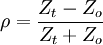 Where Zo is defined as the characteristic impedance of the transmission medium and Zt is the impedance of the termination at the far end of the transmission line. Any discontinuity can be viewed as a termination impedance and substituted as Zt. This includes abrupt changes in the characteristic impedance. As an example, a trace width on a printed circuit board doubled at its midsection would constitute a discontinuity. Some of the energy will be reflected back to the driving source; the remaining energy will be transmitted. This is also known as a scattering junction. UsageTime domain reflectometers are commonly used for in-place testing of very long cable runs, where it is impractical to dig up or remove what may be a kilometers-long cable. They are indispensable for preventive maintenance of telecommunication lines, as they can reveal growing resistance levels on joints and connectors as they corrode, and increasing insulation leakage as it degrades and absorbs moisture long before either leads to catastrophic failures. Using a TDR, it is possible to pinpoint a fault to within centimetres. TDRs are also very useful tools for Technical Surveillance Counter-Measures, where they help determine the existence and location of wire taps. The slight change in line impedance caused by the introduction of a tap or splice will show up on the screen of a TDR when connected to a phone line. TDR equipment is also an essential tool in the failure analysis of today's high-speed printed circuit boards. The signal traces on these boards are carefully crafted to emulate a transmission line. By observing reflections, any unsoldered pins of a ball grid array device can be detected. Additionally, short circuited pins can also be detected in a similar fashion. The TDR principle is used in industrial settings, in situations as diverse as the testing of integrated circuit packages to measuring liquid levels. In the former, the time domain reflectometer is used to isolate failing sites in the same. The latter is primarily limited to the process industry. TDR in level measurementIn a TDR-based level measurement device, a low-energy electromagnetic impulse generated by the sensor’s circuitry is propagated along a thin wave guide (also referred to as a probe) – usually a metal rod or a steel cable. When this impulse hits the surface of the medium to be measured, part of the impulse energy is reflected back up the probe to the circuitry which then calculates the fluid level from the time difference between the impulse sent and the impulse reflected (in nanoseconds). The sensors can output the analyzed level as a continuous analog signal or switch output signals. In TDR technology, the impulse velocity is primarily affected by the permittivity of the medium through which the pulse propagates, which can vary greatly by the moisture content and temperature of the medium. In most cases, this can be corrected for without undue difficulty. However, in complex environments, such as in boiling and/or high temperature environments, this can be a significant signal processing dilemma. In particular, determining the froth height and true collapsed liquid level in a frothy / boiling medium can be very difficult. TDR used in the Earth and Agricultural SciencesTDR is used to determine moisture content in soil and porous media, where over the last two decades substantial advances have been made; including in soils, grains and food stuffs, and in sediments. The key to TDR’s success is its ability to accurately determine the permittivity (dielectric constant) of a material from wave propagation, and the fact that there is a strong relationship between the permittivity of a material and its water content, as demonstrated in the pioneering works of Hoekstra and Delaney (1974) and Topp et al. (1980). Recent reviews and reference work on the subject include, Topp and Reynolds (1998), Noborio (2001), Pettinellia et al. (2002), Topp and Ferre (2002) and Robinson et al. (2003). The TDR method is a transmission line technique, and determines an apparent TDR permittivity (Ka) from the travel time of an electromagnetic wave that propagates along a transmission line, usually two or more parallel metal rods embedded in a soil or sediment. TDR probes are usually between 10 and 30 cm in length and connected to the TDR via a coaxial cable. TDR in Geotechnical UsageTime Domain Reflectometry (TDR) has also been utilized to monitor slope movement in a variety of geotechnical settings including highway cuts, rail beds, and open pit mines (Dowding & O'Connor, 1984, 2000a, 2000b; Kane & Beck, 1999). In stability monitoring applications using TDR, a coaxial cable is installed in a vertical borehole passing through the region of concern. The electrical impedance at any point along a coaxial cable changes with deformation of the insulator between the conductors. A brittle grout surrounds the cable to translate earth movement into an abrupt cable deformation that shows up as a detectable peak in the reflectance trace. Until recently, the technique was relatively insensitive to small slope movements and could not be automated because it relied on human detection of changes in the reflectance trace over time. Farrington and Sargand (2004) developed a simple signal processing technique using numerical derivatives to extract reliable indications of slope movement from the TDR data much earlier than by conventional interpretation. TDR in Semiconductor Device AnalysisTime Domain Reflectometry is used in semiconductor failure analysis as a non-destructive method for the location of defects in semiconductor device packages. The TDR provides an electrical signature of individual conductive traces in the device package, and is useful for determining the location of opens and shorts. References
See also
|
|
| This article is licensed under the GNU Free Documentation License. It uses material from the Wikipedia article "Time-domain_reflectometer". A list of authors is available in Wikipedia. |


