To use all functions of this page, please activate cookies in your browser.
My watch list
my.chemeurope.com
my.chemeurope.com
With an accout for my.chemeurope.com you can always see everything at a glance – and you can configure your own website and individual newsletter.
- My watch list
- My saved searches
- My saved topics
- My newsletter
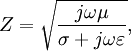
Wave impedanceThe wave impedance of an electromagnetic wave, is the ratio of the transverse components of the electric and magnetic fields (the transverse components being those at right-angles to the direction of propagation). For a transverse-electric-magnetic (TEM) plane wave travelling through a homogeneous medium, the wave impedance is everywhere equal to the intrinsic impedance of the medium. In particular, for a plane wave travelling through empty space, the wave impedance is equal to the impedance of free space. The symbol Z is used to represent it and it is expressed in units of ohms. The symbol η (eta) may be used instead of Z for wave impedance to avoid confusion with electrical impedance, although η is also the symbol for electromagnetic impedance, the light wave equivalent of wave impedance. The wave impedance is given by In terms of the parameters of an electromagnetic wave and the medium it travels through, the wave impedance is given by where μ is the magnetic permeability, ε is the electric permittivity and σ is the conductivity of the material the wave is travelling through. In the equation, j is the imaginary unit, and ω is the angular frequency of the wave. In the case of a dielectric (where conductivity is zero), the equation reduces to Product highlight
Wave impedance of free spaceIn free space,
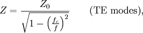
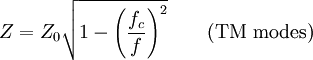
In a perfect dielectric, the wave impedance can be found by dividing Z0 into the refractive index. In anything else, the formula becomes larger and a complex number is the result. Wave impedance in an unbounded dielectricIn a perfect dielectric, In a perfect dielectric, the wave impedance can be found by dividing Z0 into the refractive index. In anything else, the formula becomes larger and a complex number is the result. Wave impedance in a waveguideFor any waveguide in the form of a hollow metal tube, (such as rectangular guide, circular guide, or double-ridge guide), the wave impedance of a travelling wave is dependent on the frequency f, but is the same throughout the guide. For transverse electric (TE) modes of propagation the wave impedance is where fc is the cut-off frequency of the mode and for (TM) modes For a waveguide or transmission line containing more than one type of dielectric medium (such as microstrip), the wave impedance will in general vary over the cross-section of the line. ReferencesThis article contains material from the Federal Standard 1037C (in support of MIL-STD-188), which, as a work of the United States Government, is in the public domain. |
|
| This article is licensed under the GNU Free Documentation License. It uses material from the Wikipedia article "Wave_impedance". A list of authors is available in Wikipedia. |


 H/m and
  F/m. So, the value of wave impedance in free space is
 F/m. So, the value of wave impedance in a perfect dielectric is