To use all functions of this page, please activate cookies in your browser.
My watch list
my.chemeurope.com
my.chemeurope.com
With an accout for my.chemeurope.com you can always see everything at a glance – and you can configure your own website and individual newsletter.
- My watch list
- My saved searches
- My saved topics
- My newsletter
PermittivityPermittivity is a physical quantity that describes how an electric field affects and is affected by a dielectric medium, and is determined by the ability of a material to polarize in response to the field, and thereby reduce the total electric field inside the material. Thus, permittivity relates to a material's ability to transmit (or "permit") an electric field. It is directly related to electric susceptibility. For example, in a capacitor, an increased permittivity allows the same charge to be stored with a smaller electric field (and thus a smaller voltage), leading to an increased capacitance. Product highlight
ExplanationIn electromagnetism, the electric displacement field D represents how an electric field E influences the organization of electrical charges in a given medium, including charge migration and electric dipole reorientation. Its relation to permittivity is where the permittivity ε is a scalar if the medium is isotropic or a second rank tensor for an anisotropic linear medium. In general, permittivity isn't a constant, as it can vary with the position in the medium, the frequency of the field applied, humidity, temperature, and other parameters. In a nonlinear medium, the permittivity can depend on the strength of the electric field. Permittivity as a function of frequency can take on real or complex values. In SI units, permittivity is measured in farads per metre (F/m). The displacement field D is measured in units of coulombs per square metre (C/m2), while the electric field E is measured in volts per metre (V/m). D and E represent the same phenomenon, namely, the interaction between charged objects. D is related to the charge densities associated with this interaction, while E is related to the forces and potential differences. Vacuum permittivityVacuum permittivity where
All three of these constants are exactly defined in SI units. Vacuum permittivity also appears in Coulomb's law as a part of the Coulomb force constant, The linear permittivity of a homogeneous material is usually given relative to that of vacuum, as a relative permittivity where
Permittivity in mediaIn the common case of isotropic media, D and E are parallel vectors and When an external electric field is applied to a real medium, a current flows. The total current flowing within the medium consists of two parts: a conduction and a displacement current. The displacement current can be thought of as the elastic response of the material to the applied electric field. As the magnitude of the externally applied electric field is increased, an increasing amount of energy is stored in the electric displacement field within the material. If the electric field is subsequently decreased, the material will release the stored electrostatic energy. The displacement current reflects the resulting change in electrostatic energy stored within the material. The electric displacement can be separated into a vacuum contribution and one arising from the material by where
It follows that the relative permittivity and susceptibility of a sample are related, Complex permittivity
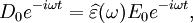
As opposed to the response of a vacuum, the response of normal materials to external fields generally depends on the frequency of the field. This frequency dependence reflects the fact that a material's polarization does not respond instantaneously to an applied field. The response must always be causal (arising after the applied field) which can be represented by a phase difference. For this reason permittivity is often treated as a complex function (since complex numbers allow specification of magnitude and phase) of the frequency of the applied field ω, where
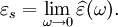
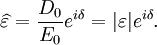
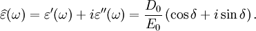
It is important to realise that the choice of sign for time-dependence dictates the sign convention for the imaginary part of permittivity. The signs used here correspond to those commonly used in physics, whereas for the engineering convention one should reverse all imaginary quantities. The response of a medium to static electric fields is described by the low-frequency limit of permittivity, also called the static permittivity At the high-frequency limit, the complex permittivity is commonly referred to as ε∞. At the plasma frequency and above, dielectrics behave as ideal metals, with electron gas behavior. The static permittivity is a good approximation for altering fields of low frequencies, and as the frequency increases a measurable phase difference δ emerges between D and E. The frequency at which the phase shift becomes noticeable depends on temperature and the details of the medium. For moderate fields strength (E0), D and E remain proportional, and Since the response of materials to alternating fields is characterized by a complex permittivity, it is natural to separate its real and imaginary parts, which is done by convention in the following way: where
The complex permittivity is usually a complicated function of frequency ω, since it is a superimposed description of dispersion phenomena occurring at multiple frequencies. The dielectric function At a given frequency, the imaginary part of Classification of materialsMaterials can be classified according to their permittivity and conductivity, σ. Materials with a large amount of loss inhibit the propagation of electromagnetic waves. In this case, generally when where
The size of the displacement current is dependent on the frequency ω of the applied field E; there is no displacement current in a constant field. In this formalism, the complex permittivity is defined as:
The above effects often combine to cause non-linear effects within capacitors. For example, dielectric absorption refers to the inability of a capacitor that has been charged for a long time to completely discharge when briefly discharged. Although an ideal capacitor would remain at zero volts after being discharged, real capacitors will develop a small voltage, a phenomenon that is also called soakage or battery action. For some dielectrics, such as many polymer films, the resulting voltage may be less than 1-2% of the original voltage. However, it can be as much as 15 - 25% in the case of electrolytic capacitors or supercapacitors. Quantum-mechanical interpretationIn terms of quantum mechanics, permittivity is explained by atomic and molecular interactions. At low frequencies, molecules in polar dielectrics are polarized by an applied electric field, which induces periodic rotations. For example, at the microwave frequency, the microwave field causes the periodic rotation of water molecules, sufficient to break hydrogen bonds. The field does work against the bonds and the energy is absorbed by the material as heat. This is why microwave ovens work very well for materials containing water. There are two maxima of the imaginary component (the absorptive index) of water, one at the microwave frequency, and the other at far ultraviolet (UV) frequency. At moderate frequencies, the energy is too high to cause rotation, yet too low to affect electrons directly, and is absorbed in the form of resonant molecular vibrations. In water, this is where the absorptive index starts to drop sharply, and the minimum of the imaginary permittivity is at the frequency of blue light (optical regime). This is why water is blue, and also why sunlight does not damage water-containing organs such as the eye.[1] At high frequencies (such as UV and above), molecules cannot relax, and the energy is purely absorbed by atoms, exciting electron energy levels. While carrying out a complete ab initio (that is, first-principles) modelling is now computationally possible, it has not been widely applied yet. Thus, a phenomological model is accepted as being an adequate method of capturing experimental behaviors. The Debye model and the Lorentz model use a 1st-order and 2nd-order (respectively) lumped system parameter linear representation (such as an RC and an LRC resonant circuit). MeasurementThe dielectric constant of a material can be found by a variety of static electrical measurements. The complex permittivity is evaluated over a wide range of frequencies by using different variants of dielectric spectroscopy, covering nearly 21 orders of magnitude from 10−6 to 1015 Hz. Also, by using cryostats and ovens, the dielectric properties of a medium can be characterized over an array of temperatures. In order to study systems for such diverse exciting fields, a number of measurement setups are used, each adequate for a special frequency range.
See also
Suggested readings
|
|||
| This article is licensed under the GNU Free Documentation License. It uses material from the Wikipedia article "Permittivity". A list of authors is available in Wikipedia. |


 (also called permittivity of free space or the electric constant) is the ratio D/E in vacuum.
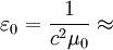 8.8541878176 × 10⁻¹²
  , which expresses the force between two unit charges separated by unit distance in vacuum.
 (also called
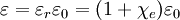
 is the
  is a scalar, but in general anisotropic media this is not the case and

 .
.
 . The definition of permittivity therefore becomes
 is the imaginary unit.
 (also
(also  ):
):
 is the imaginary part of the permittivity, which is related to the rate at which energy is absorbed by the medium (converted into thermal energy, etcetera).
 is the real part of the permittivity.
 must have poles only for frequencies with positive imaginary parts, and therefore satisfies the
  leads to absorption loss if it is positive (in the above sign convention) and gain if it is negative. More generally, the imaginary parts of the eigenvalues of the anisotropic dielectric tensor should be considered.
 , we consider the material to be a good conductor. Dielectrics are associated with lossless or low-loss materials, where
  . Those that do not fall under either limit are considered to be general media. A perfect dielectric is a material that has no conductivity, thus exhibiting only a displacement current. Therefore it stores and returns electrical energy as if it were an ideal capacitor. In the case of lossy medium, i.e. when the conduction current is not negligible, the total current density flowing is:


