To use all functions of this page, please activate cookies in your browser.
My watch list
my.chemeurope.com
my.chemeurope.com
With an accout for my.chemeurope.com you can always see everything at a glance – and you can configure your own website and individual newsletter.
- My watch list
- My saved searches
- My saved topics
- My newsletter
Acousto-opticsAcousto-optics is a branch of physics that studies the interactions between sound waves and light waves, especially the diffraction of laser light by ultrasound or sound in general.
Product highlight
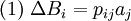
IntroductionOptics has had a very long and full history, from ancient Greece, through the renaissance and modern times[1]. As with optics, acoustics has a history of similar duration, again starting with the ancient Greeks[2]. In contrast, the acousto-optic effect has had a relatively short history, beginning with Brillouin predicting the diffraction of light by an acoustic wave, being propagated in a medium of interaction, in 1922[3]. This was then confirmed with experimentation in 1932 by Debye and Sears[4], and also by Lucas and Biquard [5]. The particular case of diffraction on the first order, under a certain angle of incidence, (also predicted by Brillouin), has been observed by Rytow in 1935. Raman and Nath (1937) have designed a general ideal model of interaction taking into account several orders. This model was developed by Phariseau (1956) for diffraction including only one diffraction order. In general, acousto-optic effects are based on the change of the refractive index of a medium due to the presence of sound waves in that medium. Sound waves produce a refractive index grating in the material, and it is this grating that is “seen” by the light wave[6]. These variations in the refractive index, due to the pressure fluctuations, may be detected optically by refraction, diffraction, and interference effects[7], reflection may also be used. The acousto-optic effect is extensively used in the measurement and study of ultrasonic waves. However, the growing principal area of interest is in acousto-optical devices for the deflection, modulation, signal processing and frequency shifting of light beams. This is due to the increasing availability and performance of lasers, which have made the acousto-optic effect easier to observe and measure. Technical progresses in both crystal growth and high frequency piezoelectric transducers have brought valuable benefits to acousto-optic components' improvements. Along with the current applications, acousto-optics presents interesting possible application. Its can be used in nondestructive testing, structural health monitoring and biomedical applications, where optically generated and optical measurements of ultrasound gives a non-contact method of imaging. The Acousto-optic effectThe acousto-optic effect is a specific case of photoelasticity, where there is a change of a materials permittivity, ε, due to a mechanical strain a. Photoelasticity is the variation of the optical indicatrix coefficients Bi caused by the strain aj given by [8] ,
where pij is the photoelastic tensor with components, i,j = 1,2,…,6. Specifically in the acousto-optic effect, the strains aj are a result of the acoustic wave which has been excited with in a transparent medium. This then gives rise to the variation of the refractive index. For a plane acoustic wave propagating along the z axis, the change in the refractive index can be expressed as [8],
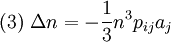
where n is the undisturbed refractive index, ω is the angular frequency, k is the wavenumber, and Δn is the amplitude of variation in the refractive index generated by the acoustic wave, and is given as[8],
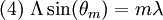
The generated refractive index, (2), gives a diffraction grating moving with the velocity given by the spread on the sound wave in the medium. Light which then passes through the transparent material, is diffracted due to this generated refraction index, forming a prominent diffraction pattern. This diffraction pattern correspond with a conventional diffraction grating at angles θn from the original direction, and is given by [7],
where λ is the wavelength of the optical wave, Λ is the wave length of the acoustic wave and m is the integer order maximum. Light diffracted by an acoustic wave of a single frequency produces two distinguished diffraction types. These are Raman-Nath diffraction and Bragg diffraction. Raman-Nath diffraction is observed with relatively low acoustic frequencies, typically less than 10MHz, and with a small acousto-optic interaction length, l, which is typically less than 1cm. This type of diffraction occurs at arbitrary angle of incidence, θ0. In contrast, Bragg diffraction occurs at higher acoustic frequencies, usually exceeding 100MHz. The observed diffraction pattern generally consists of two diffraction maxima; these are the zeroth and the first orders. However, even these two maxima only appear at definite incidence angles close to the Bragg angle, θB. The first order maximum or the Bragg maximum is formed due to a selective reflection of the light from the wave fronts of ultrasonic wavd. The Bragg angle is given by the expression [8],
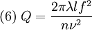
where λ is the wavelength of the incident light wave (in a vacuum), f is the acoustic frequency, v is the velocity of the acoustic wave, ni is the refractive index for the incident optical wave, and nd is the refractive index for the diffracted optical waves. In general, there is no point at which Bragg diffraction takes over from Raman-Nath diffraction. It is simply a fact that as the acoustic frequency increases, the number of observed maxima is gradually reduced due to the angular selectivity of the acousto-optic interaction increasing Traditionally, the type of diffraction, Bragg or Raman-Nath, is determined by the conditions Q >> 1 and Q << 1 respectively, where Q is given by [8],
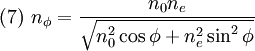
which is known as the Klein-Cook parameter. Since, in general, only the first order diffraction maximum is used in acousto-optic devices, Bragg diffraction is preferable due to the lower optical losses. However, the acousto-optic requirements for Bragg diffraction limit the frequency range of acousto-optic interaction. As a consequence, the speed of operation of acousto-optic devices is also limited. Acousto-Optic DevicesThree categories of acousto-optic devices will be discussed. They include the acousto-optic modulator, filter and deflector. Acousto-Optic ModulatorBy varying the parameters of the acoustic wave, including the amplitude, phase, frequency and polarization, properties of the optical wave may be modulated. The acousto-optic interaction also makes it possible to modulate the optical beam by both temporal and spatial modulation. A simple method of modulating the optical beam travelling through the acousto-optic device is done by switching the acoustic field on and off. When off the light beam is undiverted, the intensity of light directed at the Bragg diffraction angle is zero. When switched on and Bragg diffraction occurs, the intensity at the Bragg angle increases. So the acousto-optic device is modulating the output along the Bragg diffraction angle, switching it on and off. The device is operated as a modulator by keeping the acoustic wavelength (frequency) fixed and varying the drive power to vary the amount of light in the deflected beam [9]. There are several limitations associated with the design and performance of acousto-optic modulators. The acousto-optic medium must be designed carefully to provide maximum light intensity in a single diffracted beam. The time taken for the acoustic wave to travel across the diameter of the light beam gives a limitation on the switching speed, and hence limits the modulation bandwidth. The finite velocity of the acoustic wave means the light cannot be fully switched on or off until the acoustic wave has travel across the light beam. So to increase the bandwidth the light must be focused to a small diameter at the location of the acousto-optic interaction. This minimum focused size of the beam represents the limit for the bandwidth. Acousto-Optic FilterThe principle behind the operation of acousto-optic filters is based on the wavelength of the diffracted light being dependent on the acoustic frequency. By tuning the frequency of the acoustic wave, the desired wavelength of the optical wave can be diffracted acousto-optically. There are two types of the acousto-optic filters, the collinear and non-collinear filters. The type of filter depends on geometry of acousto-optic interaction. The polarization of the incident light can be either ordinary or extraordinary. For the definition, we assume ordinary polarization. Here the following list of symbols is used [10], α: the angle between the acoustic wave vector and the crystallographic axis z of the crystal; γ: the wedge angle between the input and output faces of the filter cell (the wedge angle is necessary for eliminating the angular shift of the diffracted beam caused by frequency changing); φ: the angle between the incident light wave vector and [110] axis of the crystal; αl: the angle between the input face of the cell and acoustic wave vector; β: the angle between deflected and non-deflected light at the central frequency; l: the transducer length. The incidence angle φ and the central frequency fi of the filter are defined by the following set of equations [10],
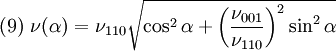
Refractive indices of the ordinary (n0) and extraordinary (ne) polarized beams are determined by taking into account their dispersive dependence. The sound velocity, v, depends on the angle α, such that [10],
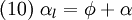
v110 and v001 are the sound velocities along the axes [110] and [001], consecutively. The value of α1 is determined by the angles φ and α [10],
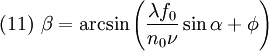
The angle β between the diffracted and non-diffracted beams defines the view field of the filter; it can be calculated from the formula [10],
Acousto-Optic deflectorsAn acousto-optic deflector spatially controls the optical beam. In the operation of an acousto-optic deflector the power driving the acoustic transducer is kept on, at a constant level, while the acoustic frequency is varied to deflect the beam to different angular positions. The acousto-optic deflector makes use of the acoustic frequency dependent diffraction angle, where a change in the angle Δθd as a function of the change in frequency Δf given as [11],
where λ and ν are the acoustic wavelength and velocity of the acoustic wave respectively.
AODs are essentially the same as acousto-optic modulators (AOMs). In an AOM, only the amplitude of the sound wave is modulated (to modulate the intensity of the diffracted laser beam), whereas in an AOD, both the amplitude and frequency are adjusted, making the engineering requirements tighter for an AOD than an AOM. References
MaterialsSome materials displaying acousto-optic effect include fused silica, arsenic trisulfide, tellurium dioxide and tellurite glasses, lead silicate, Ge55As12S33, mercury(I) chloride, lead(II) bromide, and other materials. See also
References
Categories: Diffraction | Light |
|
| This article is licensed under the GNU Free Documentation License. It uses material from the Wikipedia article "Acousto-optics". A list of authors is available in Wikipedia. |


 ,
,
 ,
,
 ,
,
 ,
,
![(5) \ \sin \theta_B = - \frac{\lambda f}{2 n_i \nu}\left[ 1+\frac{\nu^2}{\lambda^2 f^2 } \left( n_i^2 - n_d^2 \right) \right]](images/math/3/a/2/3a2b2051ff5ba304c59f87ee66bdd0e4.png) ,
,
 ,
,
![(8) \ f_i(\phi)=\frac{\nu}{\lambda}\left[n_\phi\cos(\phi+\alpha)\pm\sqrt{n_0^2 - n_\phi^2(\phi)\sin^2(\phi+\alpha)}\right]](images/math/c/6/7/c677e4c2595c0efde876ffe89e9d9efd.png)
Last viewed


