To use all functions of this page, please activate cookies in your browser.
My watch list
my.chemeurope.com
my.chemeurope.com
With an accout for my.chemeurope.com you can always see everything at a glance – and you can configure your own website and individual newsletter.
- My watch list
- My saved searches
- My saved topics
- My newsletter
Flue gas stackA flue gas stack is a type of chimney, a vertical pipe, channel or similar structure through which combustion product gases called flue gases are exhausted to the outside air. Flue gases are produced when coal, oil, natural gas, wood or any other fuel is combusted in an industrial furnace, a power plant's steam-generating boiler, or other large combustion device. Flue gas is usually composed of carbon dioxide (CO2) and water vapor as well as nitrogen and excess oxygen remaining from the intake combustion air. It also contains a small percentage of pollutants such as particulate matter, carbon monoxide, nitrogen oxides and sulfur oxides. The flue gas stacks are often quite tall, up to 400 meters (1300 feet) or more, so as to disperse the exhaust pollutants over a greater area and thereby reduce the concentration of the pollutants to the levels required by governmental environmental policies and regulations. When the flue gases are exhausted from stoves, ovens, fireplaces, or other small sources within residential abodes, restaurants, hotels, or other public buildings and small commercial enterprises, their flue gas stacks are referred to as chimneys. Product highlight
HistoryThe first industrial chimneys were built in the mid-17th century when it was first understood how they could improve the combustion of a furnace by increasing the draft (draught) of air into the combustion zone. [2] As such, they played an important part in the development of reverberatory furnaces and a coal-based metallurgical industry, one of the key sectors of the early Industrial Revolution. Most 18th century industrial chimneys (now commonly referred to as flue gas stacks) were built into the walls of the furnace much like a domestic chimney. The first free-standing industrial chimneys were probably those erected at the end of the long condensing flues associated with smelting lead. The powerful association between industrial chimneys and the characteristic smoke-filled landscapes of the industrial revolution was due the universal application of the steam engine for most manufacturing processes. The chimney is part of a steam-generating boiler, and its evolution is closely linked to increases in the power of the steam engine. The chimneys of Thomas Newcomen’s steam engine were incorporated into the walls of the engine house. The taller, free-standing industrial chimneys that appeared in the early 19th century were related to the changes in boiler design associated with James Watt’s "double-powered" engines, and they continued to grow in stature throughout the Victorian period. Decorative embellishments are a feature of many industrial chimneys from the 1860s, with over-sailing caps and patterned brickwork. The invention of fan-assisted forced draft (draught) in the early 20th century removed the industrial chimney's original function, that of drawing air into the steam-generating boilers or other furnaces. With the replacement of the steam engine as a prime mover, first by diesel engines and then by electric motors, the early industrial chimneys began to disappear from the industrial landscape. Building materials changed from stone and brick to steel and later reinforced concrete, and the height of the industrial chimney was determined by the need to disperse combustion flue gases to comply with governmental air pollution control regulations. Flue gas stack draft (or draught)
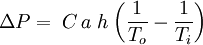
The combustion flue gases inside the flue gas stacks are much hotter than the ambient outside air and therefore less dense than the ambient air. That causes the bottom of the vertical column of hot flue gas to have a lower pressure than the pressure at the bottom of a corresponding column of outside air. That higher pressure outside the chimney is the driving force that moves the required combustion air into the combustion zone and also moves the flue gas up and out of the chimney. That movement or flow of combustion air and flue gas is called "natural draft (or draught)", "natural ventilation", "chimney effect", or "stack effect". The taller the stack, the more draft (or draught) is created. The equation below provides an approximation of the pressure difference, ΔP, (between the bottom and the top of the flue gas stack) that is created by the draft:[3][4]
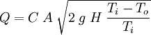
The above equation is an approximation because it assumes that the molar mass of the flue gas and the outside air are equal and that the pressure drop through the flue gas stack is quite small. Both assumptions are fairly good but not exactly accurate. The flue gas flow rate induced by the draftAs a "first guess" approximation, the following equation can be used to estimate the flue gas flow rate induced by the draft of a flue gas stack. The equation assumes that the molar mass of the flue gas and the outside air are equal and that the frictional resistance and heat losses are negligible:[5]
Designing chimneys and stacks to provide the correct amount of natural draft involves a great many factors such as:
The calculation of many of the above design factors requires trial-and-error reiterative methods. Governmental agencies in most countries have specific codes which govern how such design calculations must be performed. Many non-governmental organizations also have codes governing the design of chimneys and stacks (notably, the ASME codes). Other items of interestIt should be noted that not all fuel-burning industrial equipment rely upon natural draft. Many such equipment items use large fans or blowers to accomplish the same objectives, namely: the flow of combustion air into the combustion chamber and the flow of the hot flue gas out of the chimney or stack. A great many power plants are equipped with facilities for the removal of sulfur dioxide (i.e., flue gas desulfurization) and nitrogen oxides (i.e, selective catalytic reduction, exhaust gas recirculation, thermal deNOx, or low NOx burners). At such power plants, it is possible to use a cooling tower as a flue gas stack. Examples can be seen in Germany at the Power Station Staudinger Grosskrotzenburg and at the Rostock Power Station. Power plants without flue gas purification, would experience serious corrosion in such cooling towers. In the United States and a number of other countries, atmospheric dispersion modeling[6] studies are required to determine the flue gas stack height needed to comply with the local air pollution regulations. The United States also limits the maximum height of a flue gas stack to what is known as the "Good Engineering Practice (GEP)" stack height.[7][8] In the case of existing flue gas stacks that exceed the GEP stack height, any air pollution dispersion modeling studies for such stacks must use the GEP stack height rather than the actual stack height. See also
References
|
|||||||||||||||||||||||||||||||
| This article is licensed under the GNU Free Documentation License. It uses material from the Wikipedia article "Flue_gas_stack". A list of authors is available in Wikipedia. |


Last viewed


