To use all functions of this page, please activate cookies in your browser.
My watch list
my.chemeurope.com
my.chemeurope.com
With an accout for my.chemeurope.com you can always see everything at a glance – and you can configure your own website and individual newsletter.
- My watch list
- My saved searches
- My saved topics
- My newsletter
Rankine cycleThe Rankine cycle is a thermodynamic cycle which converts heat into work. The heat is supplied externally to a closed loop, which usually uses water as the working fluid. Almost all coal and nuclear power stations use this cycle for power generation. It is named after William John Macquorn Rankine, a Scottish polymath. Product highlight
Description
A Rankine cycle describes a model of the operation of steam heat engines most commonly found in power generation plants. Common heat sources for power plants using the Rankine cycle are coal, natural gas, oil, and nuclear. The Rankine cycle is sometimes referred to as a practical Carnot cycle as, when an efficient turbine is used, the TS diagram will begin to resemble the Carnot cycle. The main different is that a pump is used to compress the liquid water. This requires about 100 times less energy that compressing a gas in a compressor (as in the Carnot cycle). The efficiency of a Rankine cycle is usually limited by the working fluid. Without the pressure going super critical the temperature range the cycle can operate over is quite small, turbine entry temperatures are typically 565°C (the creep limit of stainless steel) and condenser temperatures are around 30°C. This gives a theoretical Carnot efficiency of around 63% compared with an actual efficiency of 42% for a modern coal-fired power station. This low turbine entry temperature (compared with a gas turbine) is why the Rankine cycle is often used as a bottoming cycle in combined cycle gas turbine power stations. The working fluid in a Rankine cycle follows a closed loop and is re-used constantly. The water vapor often seen billowing from power stations is generated by the cooling systems and represents the waste heat that could not be converted to useful work. Note that steam is invisible until it comes in contact with cool, saturated air, at which point it condenses and forms the white billowy clouds seen leaving cooling towers. While many substances could be used in the Rankine cycle, water is usually the fluid of choice due to its favorable properties, such as nontoxic and unreactive chemistry, abundance, and low cost, as well as its thermodynamic properties. One of the principle advantages it holds over other cycles is that during the compression stage relatively little work is required to drive the pump, due to the working fluid being in its liquid phase at this point. By condensing the fluid to liquid, the work required by the pump will only consume approximately 1% of the turbine power and so give a much higher efficiency for a real cycle. The benefit of this is lost somewhat due to the lower heat addition temperature. Gas turbines, for instance, have turbine entry temperatures approaching 1500°C. Nonetheless, the efficiencies of steam cycles and gas turbines are fairly well matched. Processes of the Rankine cycle
There are four processes in the Rankine cycle, each changing the state of the working fluid. These states are identified by number in the diagram to the right.
In an ideal Rankine cycle the pump and turbine would be isentropic, i.e., the pump and turbine would generate no entropy and hence maximise the net work output. Processes 1-2 and 3-4 would be represented by vertical lines on the Ts diagram and more closely resemble that of the Carnot cycle. The Rankine cycle shown here prevents the vapor ending up in the superheat region after the expansion in the turbine [1], which reduces the energy removed by the condensers. Variables
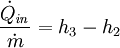
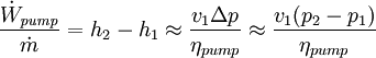
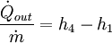
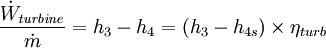
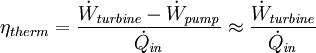
EquationsEach of the first four equations[1] is easily derived from the energy and mass balance for a control volume. The fifth equation defines the thermodynamic efficiency of the cycle as the ratio of net power output to heat input. As the work required by the pump is often around 1% of the turbine work output, equation 5 can be simplified.
Real Rankine cycle (non-ideal)In a real Rankine cycle, the compression by the pump and the expansion in the turbine are not isentropic. In other words, these processes are non-reversible and entropy is increased during the two processes. This somewhat increases the power required by the pump and decreases the power generated by the turbine. It also makes calculations more involved and difficult. In particular the efficiency of the steam turbine will be limited by water droplet formation. As the water condenses, water droplets hit the turbine blades at high speed causing pitting and erosion, gradually decreasing the efficiency of the turbine. The easiest way to overcome this problem is by superheating the steam. On the Ts diagram above, state 3 is above a two phase region of steam and water so after expansion the steam will be very wet. By superheating, state 3 will move to the right of the diagram and hence produce a dryer steam after expansion. Variations of the basic Rankine cycle
The overall thermodynamic efficiency (of almost any cycle) can be increased by raising the average heat input temperature Rankine cycle with reheatIn this variation, two turbines work in series. The first accepts vapor from the boiler at high pressure. After the vapor has passed through the first turbine, it re-enters the boiler and is reheated before passing through a second, lower pressure turbine. Among other advantages, this prevents the vapor from condensing during its expansion which can seriously damage the turbine blades, and improves the efficiency of the cycle. Regenerative Rankine cycleThe regenerative Rankine cycle is so named because after emerging from the condenser (possibly as a subcooled liquid) the working fluid is heated by steam tapped from the hot portion of the cycle. On the diagram shown, the fluid at 2 is mixed with the fluid at 4 (both at the same pressure) to end up with the saturated liquid at 7. The Regenerative Rankine cycle (with minor variants) is commonly used in real power stations. Another variation is where 'bleed steam' from between turbine stages is sent to feedwater heaters to preheat the water on its way from the condenser to the boiler. Organic Rankine cycleThe organic Rankine cycle (ORC) uses an organic fluid such as pentane[1] or butane[2] in place of water and steam. This allows use of lower-temperature heat sources, such as solar ponds, which typically operate at around 70–90 °C[3]. The efficiency of the cycle is much lower as a result of the lower temperature range, but this can be worthwhile because of the lower cost involved in gathering heat at this lower temperature. Alternatively, fluids can be used that have boiling points above water, and this may have thermodynamic benefits. The Rankine cycle does not restrict the working fluid in its definition, so the inclusion of an "organic" cycle is simply a marketing concept that should not be regarded as a separate thermodynamic cycle.
References
|
||||||||||||||||||||||||||||||||||||
| This article is licensed under the GNU Free Documentation License. It uses material from the Wikipedia article "Rankine_cycle". A list of authors is available in Wikipedia. | ||||||||||||||||||||||||||||||||||||


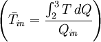 of that cycle. Increasing the temperature of the steam into the superheat region is a simple way of doing this. There are also variations of the basic Rankine cycle which are designed to raise the thermal efficiency of the cycle in this way; two of these are described below.


