To use all functions of this page, please activate cookies in your browser.
My watch list
my.chemeurope.com
my.chemeurope.com
With an accout for my.chemeurope.com you can always see everything at a glance – and you can configure your own website and individual newsletter.
- My watch list
- My saved searches
- My saved topics
- My newsletter
Circular polarizationIn electrodynamics, circular polarization (also circular polarisation) of electromagnetic radiation is a polarization such that the tip of the electric field vector, at a fixed point in space, describes a circle as time progresses. The electric vector, at one point in time, describes a helix along the direction of wave propagation (see the polarization article for pictures). The magnitude of the electric field vector is constant as it rotates. Circular polarization is a limiting case of the more general condition of elliptical polarization. The other special case is the easier-to-understand linear polarization. Circular (and elliptical) polarization is possible because the propagating electric (and magnetic) fields can have two orthogonal components with independent amplitudes and phases (and the same frequency). A circularly polarized wave may be resolved into two linearly polarized waves, of equal amplitude, in phase quadrature (90 degrees apart) and with their planes of polarization at right angles to each other. Circular polarization may be referred to as right or left, depending on the direction in which the electric field vector rotates. Unfortunately, two opposing historical conventions exist. In physics and astronomy, polarization is defined as seen from the receiver, such as a telescope or radio telescope. By this definition, if you could stop time and look at the electric field along the beam, it would trace a helix which is the same shape as the same-handed screw. For example, right circular polarization produces a right threaded (or forward threaded) screw. In the U.S., Federal Standard 1037C also defines the handedness of circular polarization in this manner. In electrical engineering, however, it is more common to define polarization as seen from the source, such as from a transmitting antenna. To avoid confusion, it is good practice to specify "as seen from the receiver" (or transmitter) when discussing polarization matters. Product highlight
FM radioThe term "circular polarization" is often used erroneously to describe mixed polarity signals used mostly in FM radio (87.5 to 108.0 MHz), where a vertical and a horizontal component are propagated simultaneously by a single or a combined array. This has the effect of producing greater penetration into buildings and difficult reception areas than a signal with just one plane of polarization. Circular dichroism
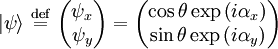
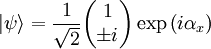
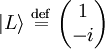
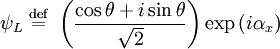
Circular dichroism (CD), is the differential absorption of left- and right-handed circularly polarized light. It is a form of spectroscopy used to determine the optical isomerism and secondary structure of molecules. In general, this phenomenon will be exhibited in absorption bands of any optically active molecule. As a consequence, circular dichroism is exhibited by biological molecules, because of the dextrorotary (e.g. some sugars) and levorotary (e.g. some amino acids) molecules they contain. Noteworthy as well is that a secondary structure will also impart a distinct CD to its respective molecules. Therefore, the alpha helix of proteins and the double helix of nucleic acids have CD spectral signatures representative of their structures. Mathematical description of circular polarizationThe classical sinusoidal plane wave solution of the electromagnetic wave equation for the electric and magnetic fields is for the magnetic field, where k is the wavenumber, is the angular frequency of the wave, and c is the speed of light. Here is the amplitude of the field and is the Jones vector in the x-y plane. If αy is rotated by π / 2 radians with respect to αx and the x amplitude equals the y amplitude the wave is circularly polarized. The Jones vector is where the plus sign indicates right circular polarization and the minus sign indicates left circular polarization. In the case of circular polarization, the electric field vector of constant magnitude rotates in the x-y plane. If unit vectors are defined such that and then the polarization state can written in the "R-L basis" as where and
References
See also
|
|
| This article is licensed under the GNU Free Documentation License. It uses material from the Wikipedia article "Circular_polarization". A list of authors is available in Wikipedia. |


![\mathbf{E} ( \mathbf{r} , t ) = \mid \mathbf{E} \mid \mathrm{Re} \left \{ |\psi\rangle \exp \left [ i \left ( kz-\omega t \right ) \right ] \right \}](images/math/f/0/7/f07592ed67ae0ecb6ebb466182fcfbde.png)


 .
.


