To use all functions of this page, please activate cookies in your browser.
My watch list
my.chemeurope.com
my.chemeurope.com
With an accout for my.chemeurope.com you can always see everything at a glance – and you can configure your own website and individual newsletter.
- My watch list
- My saved searches
- My saved topics
- My newsletter
Heat engine
A heat engine is a physical or theoretical device that converts thermal energy to mechanical output. The mechanical output is called work, and the thermal energy input is called heat. Heat engines typically run on a specific thermodynamic cycle. Heat engines are often named after the thermodynamic cycle they are modeled by. They often pick up alternate names, such as gasoline/petrol, turbine, or steam engines. Heat engines can generate heat inside the engine itself or it can absorb heat from an external source. Heat engines can be open to the atmospheric air or sealed and closed off to the outside (Open or closed cycle). In engineering and thermodynamics, a heat engine performs the conversion of heat energy to mechanical work by exploiting the temperature gradient between a hot "source" and a cold "sink". Heat is transferred from the source, through the "working body" of the engine, to the sink, and in this process some of the heat is converted into work by exploiting the properties of a working substance (usually a gas or liquid).
Product highlight
OverviewHeat engines are often confused with the cycles they attempt to mimic. Typically when describing the physical device the term 'engine' is used. When describing the model the term 'cycle' is used. In thermodynamics, heat engines are often modeled using a standard engineering model such as the Otto cycle. The theoretical model can be refined and augmented with actual data from an operating engine, using tools such as an indicator diagram. Since very few actual implementations of heat engines exactly match their underlying thermodynamic cycles, one could say that a thermodynamic cycle is an ideal case of a mechanical engine. In any case, fully understanding an engine and its efficiency requires gaining a good understanding of the (possibly simplified or idealized) theoretical model, the practical nuances of an actual mechanical engine, and the discrepancies between the two. In general terms, the larger the difference in temperature between the hot source and the cold sink, the larger is the potential thermal efficiency of the cycle. On Earth, the cold side of any heat engine is limited to close to the ambient temperature of the environment, or not much lower than 300 kelvins, so most efforts to improve the thermodynamic efficiencies of various heat engines focus on increasing the temperature of the source, within material limits. The efficiency of various heat engines proposed or used today ranges from 3 percent [1](97 percent waste heat) for the OTEC ocean power proposal through 25 percent for most automotive engines, to 45 percent for a supercritical coal plant, to about 60 percent for a steam-cooled combined cycle gas turbine. All of these processes gain their efficiency (or lack thereof) due to the temperature drop across them. OTEC uses the temperature difference of ocean water on the surface and ocean water from the depths, a small difference of perhaps 25 degrees Celsius, and so the efficiency must be low. The combined cycle gas turbines use natural-gas fired burners to heat air to near 1530 degrees Celsius, a difference of a large 1500 degrees Celsius, and so the efficiency can be large when the steam-cooling cycle is added in. [2] Everyday examplesExamples of everyday heat engines include: the steam engine, the diesel engine, and the gasoline (petrol) engine in an automobile. A common toy that is also a heat engine is a drinking bird. All of these familiar heat engines are powered by the expansion of heated gases. The general surroundings are the heat sink, providing relatively cool gases which, when heated, expand rapidly to drive the mechanical motion of the engine. Examples of heat enginesIt is important to note that although some cycles have a typical combustion location (internal external), they often can be implemented as the other combustion cycle. For example, John Ericsson developed an external heated engine running on a cycle very much like the earlier Diesel cycle. In addition, the externally heated engines can often be implemented in open or closed cycles. What this boils down to is there are thermodynamic cycles and a large number of ways of implementing them with mechanical devices called engines. Phase change cyclesIn these cycles and engines, the working fluids are gases and liquids. The engine converts the working fluid from a gas to a liquid.
Gas only cyclesIn these cycles and engines the working fluid are always like gas:
Liquid only cyclesIn these cycles and engines the working fluid are always like liquid:
Electron cycles
Magnetic cycles
Cycles used for refrigerationA refrigerator is a heat pump: a heat engine in reverse. Work is used to create a heat differential. Many cycles can run in reverse to move heat from the cold side to the hot side, making the cold side cooler and the hot side hotter. Internal combustion engine versions of these cycles are, by their nature, not reversible.
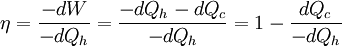
Evaporative Heat EnginesThe Barton Evaporation Engine is a heat engine based on a cycle producing power and cooled moist air from the evaporation of water into hot dry air. EfficiencyThe efficiency of a heat engine relates how much useful power is output for a given amount of heat energy input. From the laws of thermodynamics:
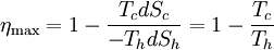
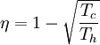
In other words, a heat engine absorbs heat energy from the high temperature heat source, converting part of it to useful work and delivering the rest to the cold temperature heat sink. In general, the efficiency of a given heat transfer process (whether it be a refrigerator, a heat pump or an engine) is defined informally by the ratio of "what you get" to "what you put in." In the case of an engine, one desires to extract work and puts in a heat transfer. The theoretical maximum efficiency of any heat engine depends only on the temperatures it operates between. This efficiency is usually derived using an ideal imaginary heat engine such as the Carnot heat engine, although other engines using different cycles can also attain maximum efficiency. Mathematically, this is because in reversible processes, the change in entropy of the cold reservoir is the negative of that of the hot reservoir (i.e., dSc = − dSh), keeping the overall change of entropy zero. Thus: where Th is the absolute temperature of the hot source and Tc that of the cold sink, usually measured in kelvin. Note that dSc is positive while dSh is negative; in any reversible work-extracting process, entropy is overall not increased, but rather is moved from a hot (high-entropy) system to a cold (low-entropy one), decreasing the entropy of the heat source and increasing that of the heat sink. The reasoning behind this being the maximal efficiency goes as follows. It is first assumed that if a more efficient heat engine than a Carnot engine is possible, then it could be driven in reverse as a heat pump. Mathematical analysis can be used to show that this assumed combination would result in a net decrease in entropy. Since, by the second law of thermodynamics, this is forbidden, the Carnot efficiency is a theoretical upper bound on the efficiency of any process. Empirically, no engine has ever been shown to run at a greater efficiency than a Carnot cycle heat engine. Here are two plots, Figure 2 and Figure 3, for the Carnot cycle efficiency. One plot indicates how the cycle efficiency changes with an increase in the heat addition temperature for a constant compressor inlet temperature, while the other indicates how the cycle efficiency changes with an increase in the heat rejection temperature for a constant turbine inlet temperature. Other criteria of heat engine performanceOne problem with the ideal Carnot efficiency as a criterion of heat engine performance is the fact that by its nature, any maximally-efficient Carnot cycle must operate at an infinitesimal temperature gradient. This is because any transfer of heat between two bodies at differing temperatures is irreversible, and therefore the Carnot efficiency expression only applies in the infinitesimal limit. The major problem with that is that the object of most heat engines is to output some sort of power, and infinitesimal power is usually not what is being sought. A different measure of heat engine efficiency is given by the endoreversible process, which is identical to the Carnot cycle except in that the two processes of heat transfer are not reversible. As derived in Callen (1985), the efficiency for such a process is given by: (Note: This equation is quite frequently traced to a paper by F.L. Curzon and B. Ahlborn, American Journal of Physics, vol. 43, pp. 22-24 (1975). The book by Herbert Callen probably copied from this paper. In a 1996 review paper by Adrian Bejan (J. Appl. Phys., vol. 79, pp. 1191-1218, 1 Feb. 1996), Adrian Bejan pointed out that this equation was also derived by P. Chambadal and I.I. Novikov earlier than Curzon and Ahlborn in the 1950s. Probably, this equation was just re-discovered by Curzon and Ahlborn in 1975. Therefore, some scientists call this efficiency the Chambadal-Novikov-Curzon-Ahlborn efficiency.) This model does a better job of predicting how well real-world heat engines can do, as can be seen in the following table (Callen): (Note: This table appeared in the paper by F.L. Curzon and B. Ahlborn, American Journal of Physics, vol. 43, pp. 22-24 (1975). The book by Herbert Callen probably copied from this paper.)
As shown, the endoreversible efficiency much more closely models the observed data. Heat engine enhancementsEngineers have studied the various heat engine cycles extensively in an effort to improve the amount of usable work they could extract from a given power source. The Carnot Cycle limit cannot be reached with any gas-based cycle, but engineers have worked out at least two ways to possibly go around that limit, and one way to get better efficiency without bending any rules. 1) Increase the temperature difference in the heat engine. The simplest way to do this is to increase the hot side temperature, and is the approach used in modern combined-cycle gas turbines. Unfortunately, NOx production and material limits (melting the turbine blades) place a hard limit to how hot you can make a workable heat engine. Modern gas turbines are about as hot as they can become and still maintain acceptable NOx pollution levels. Another way of increasing efficiency is to lower the output temperature. One new method of doing so is to use mixed chemical working fluids, and then exploit the changing behavior of the mixtures. One of the most famous is the so-called Kalina Cycle, which uses a 70/30 mix of ammonia and water as its working fluid. This mixture allows the cycle to generate useful power at considerably lower temperatures than most other processes. 2) Exploit the physical properties of the working fluid. The most common such exploit is the use of water above the so-called critical point, or so-called supercritical steam. The behavior of fluids above their critical point changes radically, and with materials such as water and carbon dioxide it is possible to exploit those changes in behavior to extract greater thermodynamic efficiency from the heat engine, even if it is using a fairly conventional Brayton or Rankine cycle. A newer and very promising material for such applications is CO2. SO2 and xenon have also been considered for such applications, although SO2 is a little toxic for most. 3) Exploit the chemical properties of the working fluid. A fairly new and novel exploit is to use exotic working fluids with advantageous chemical properties. One such is nitrogen dioxide (NO2), a toxic component of smog, which has a natural dimer as di-nitrogen tetraoxide (N2O4). At low temperature, the N2O4 is compressed and then heated. The increasing temperature causes each N2O4 to break apart into two NO2 molecules. This lowers the molecular weight of the working fluid, which drastically increases the efficiency of the cycle. Once the NO2 has expanded through the turbine, it is cooled by the heat sink, which causes it to recombine into N2O4. This is then fed back to the compressor for another cycle. Such species as aluminum bromide (Al2Br6), NOCl, and Ga2I6 have all been investigated for such uses. To date, their drawbacks have not warranted their use, despite the efficiency gains that can be realized. [3] Heat engine processes
Each process is one of the following:
References
See also
Categories: Heat | Thermodynamics |
||||||||||||||||||||||||||||||||||||||||||||||||||||||||||||||||||||||||||||||||||||||||||||||||||||||||||||||
| This article is licensed under the GNU Free Documentation License. It uses material from the Wikipedia article "Heat_engine". A list of authors is available in Wikipedia. | ||||||||||||||||||||||||||||||||||||||||||||||||||||||||||||||||||||||||||||||||||||||||||||||||||||||||||||||


 (Note: Units
 Last viewed


