To use all functions of this page, please activate cookies in your browser.
My watch list
my.chemeurope.com
my.chemeurope.com
With an accout for my.chemeurope.com you can always see everything at a glance – and you can configure your own website and individual newsletter.
- My watch list
- My saved searches
- My saved topics
- My newsletter
Stirling engine
In the family of heat engines, 'Stirling engine' defines a closed-cycle regenerative hot air engine. In this context; "hot air" may be taken to include other permanent gasses, "closed-cycle" to mean the working fluid is permanently contained within the system, and "regenerative" to refer to the use of an internal heat exchanger - the regenerator. Product highlightBackgroundIn the conversion of heat into mechanical work, the Stirling engine has the potential to achieve the highest efficiency of any real heat engine, theoretically up to the full Carnot efficiency, though in practice this is limited by non-ideal properties of the working gas and engine materials, such as friction, thermal conductivity, tensile strength, creep, melting point, etc. Though traditionally classified as an external combustion engine the Stirling engine can run on any heat source, including solar, chemical and nuclear. There are many possible implementations of the Stirling engine most of which fall into the category of reciprocating piston engine. In contrast to internal combustion engines, Stirling engines have the potential to be more energy efficient, quieter, and more reliable with lower maintenance requirements. They are preferred for certain niche applications that value these unique advantages, particularly in cases where the primary objective is not to minimize the capital cost per unit power ($/kW), but rather to minimize the cost per unit energy generated by the engine ($/kWh). Compared to an internal combustion engine of a given power rating, Stirling engines currently have a higher capital cost and are usually larger and heavier; therefore, the engine technology is rarely competitive on this basis alone. For some applications, however, a proper cost-benefit analysis can favor a Stirling engine over an internal combustion engine. In recent years, the advantages of Stirling engines have become increasingly significant, given the general rise in energy costs, energy shortages and environmental concerns such as climate change. These growing interests in Stirling technology have fostered the ongoing research and development of Stirling devices. The applications include water pumping, space-based astronautics, and electrical generation from plentiful energy sources that are incompatible with the internal combustion engine, such as solar energy, agricultural waste and domestic refuse. Another useful characteristic of the Stirling engine is that the cycle is reversible. Which means that if supplied with mechanical power, it can function as a heat pump. Experiments have been performed using wind power driving a Stirling cycle heat pump for domestic heating and air conditioning. In the late 1930s, the Philips Corporation of the Netherlands successfully utilized the Stirling cycle in cryogenic applications.[1] HistoryStirling's air engine (as it is referred to in early text books - see hot air engine history) was invented by Reverend Dr. Robert Stirling and patented by him in 1816. When the name became simplified to Stirling engine is not known, but may be as recently as the mid twentieth century when the Philips company began to experiment with working fluids other than air - the instruction book for their MP1002CA (see below) still refers to it as an 'air engine'. The main subject of that original patent was a heat exchanger which Stirling called the "economiser" for its enhancement of fuel economy in a variety of applications. The patent also described in detail the employment of one form of the economiser in an air engine, in which application it is now commonly known as a regenerator. An engine built by Stirling was put to work pumping water in a quarry in 1818. Subsequent development by Robert Stirling and his brother James, an engineer, resulted in patents for various improved configurations of the original engine, including pressurisation which by 1845 had sufficiently increased the power output for it to successfully drive all the machinery at a Dundee iron foundry. As well as conserving fuel, the inventors sought to create a safer alternative to the steam engines of the time whose boilers frequently exploded with dire consequences, often including loss of life. However, the need for the Stirling engine to run at a very high temperature to maximize power and efficiency exposed limitations in the materials of the day and the few engines which were built in those early years had rather short and troublesome lives. In particular, 'hot end' failures occurred more frequently than could be tolerated, albeit with far less disastrous results than a steam boiler explosion. Though it ultimately failed as a competitor to the steam engine in the field of industrial scale prime movers, during the latter nineteenth and early twentieth centuries smaller engines of the Stirling/hot air type (the boundary between the two is often blurred as in many the regenerator is of dubious efficiency or omitted altogether) were produced in large numbers, finding applications wherever a reliable source of low to medium power was required, most commonly perhaps for raising water. These generally operated at lower temperatures so as not to tax available materials and thus tended to be rather inefficient, their major selling point being that in contrast to a steam engine, they could be operated safely by anybody capable of managing the fire in a domestic range. As the century wore on, this role was eventually usurped by the electric motor and small internal combustion engines and by the late 1930s the Stirling engine was a largely forgotten scientific curiosity represented only by toys and a few small ventilating fans. At this time Philips, the large Dutch electrical and electronic manufacturer, was seeking to expand the market for its radio sets into areas where mains electricity was unknown and the supply of short-lived batteries uncertain. Philips’ management decided that what was needed was a low-powered portable generator and tasked a group of engineers at the company research lab (the Nat. Lab) in Eindhoven to investigate the practicalities. Reviewing various prime movers old and new, each was rejected for one reason or another until the Stirling engine was considered. Inherently quiet and capable of running from any heat source (common lamp oil “cheap and available everywhere” was favoured), it seemed to offer real possibilities. Encouraged by their first experimental engine, which produced 16 watts of shaft power from a bore and stroke of 30x25mm, a development program was set in motion. Remarkably, this work continued throughout World War II and by the late 1940s they had an engine – the Type 10 – which was sufficiently developed to be handed over to Philips’ subsidiary Johan de Witt in Dordrecht to be ‘productionised’ and incorporated into a generator set as originally planned. The set progressed through three prototypes (102A, B, and C), with the production version, rated at 200 watts electrical output from a bore and stroke of 55x27mm, being designated MP1002CA (affectionately known as the 'Bungalow set'). Production of an initial batch began in 1951, but it became clear that they could not be made at a price that the market would support, besides which the advent of transistor radios with their much lower power requirements meant that the whole raison d'être for the set was fast disappearing. Though the MP1002CA may have been a dead end, it represents the start of the modern age of Stirling engine development. Philips went on to develop the Stirling engine for a wide variety of applications including vehicles, but only ever achieved any commercial success with the 'reversed Stirling engine' cryocooler. They did however take out a large number of patents and amass a wealth of information relating to Stirling engine technology, which was later licensed to other companies. It was also employed in reverse as a heat pump to produce early refrigeration.[citation needed] Functional descriptionThe engine cycleSince the Stirling engine is a closed cycle, it contains a fixed mass of gas called the "working fluid", most commonly air, hydrogen or helium. In normal operation, the engine is sealed and no gas enters or leaves the engine. No valves are required, unlike other types of piston engines. The Stirling engine, like most heat-engines, cycles through four main processes: cooling, compression, heating and expansion. This is accomplished by moving the gas back and forth between hot and cold heat exchangers. The hot heat exchanger is in thermal contact with an external heat source, e.g. a fuel burner, and the cold heat exchanger being in thermal contact with an external heat sink, e.g. air fins. A change in gas temperature will cause a corresponding change in gas pressure, while the motion of the piston causes the gas to be alternately expanded and compressed. The gas follows the behavior described by the gas laws which describe how a gas's pressure, temperature and volume are related. When the gas is heated, because it is in a sealed chamber, the pressure rises and this then acts on the power piston to produce a power stroke. When the gas is cooled the pressure drops and this means that less work needs to be done by the piston to compress the gas on the return stroke, thus yielding a net power output. When one side of the piston is open to the atmosphere, the operation is slightly different. As the sealed volume of working gas comes in contact with the hot side, it expands, doing work on both the piston and on the atmosphere. When the working gas contacts the cold side, the atmosphere does work on the gas and "compresses" it. Atmospheric pressure, which is greater than the cooled working gas, pushes on the piston. To summarize, the Stirling engine uses the temperature difference between its hot end and cold end to establish a cycle of a fixed mass of gas expanding and contracting within the engine, thus converting thermal energy into mechanical power. The greater the temperature difference between the hot and cold sources, the greater the potential Carnot cycle efficiency.
Small demonstration engines have been built which will run on a temperature difference of as little as 7 °C, e.g. between the palm of a hand and the surrounding air, or between room temperature and melting water ice. [2] [3] [4] PressurisationMost high performance Stirling engines are pressurised, that is the mean pressure of the working fluid is above atmospheric pressure. This increases the mass of working fluid processed per cycle, thus, all other things being equal, the engine produces more power. Unfortunately all other things seldom are equal, and to realise the potential of pressurisation larger heat exhangers (including the regenerator) are required. This inevitably increases dead space and possibly gas flow resistance, both of which tend to reduce power output. Like most aspects of Stirling engine design, optimisation of this aspect is a delicate balancing act between often conflicting requirements. It was experimenting with pressurisation which initially led Philips to move from atmospheric air to other gases for the working fluid. At high temperatures and pressures, the oxygen in air tended to combine with any lubricating oil that made its way past the piston seals, giving problems with clogging the heat exchangers or even the possibility of an explosion. It was later found that some gases, particularly hydrogen and helium, offered other advantages over air.
The Stirling cycle
The idealised or "text book" Stirling cycle is a thermodynamic cycle with two isochores (constant volume) and two isotherms (constant temperature). It is the most efficient thermodynamic cycle capable of practical implementation in an engine - its theoretical efficiency equaling that of the hypothetical Carnot cycle. However technical issues limit its efficiency when applied - for instance a simpler mechanism may be favored over attaining a close fit to the theoretical cycle. The regeneratorIn a Stirling engine, the regenerator is an internal heat exchanger and temporary store placed between the hot and cold spaces such that the working fluid passes through it first in one direction then the other. Its function is to retain within the system that heat which would otherwise be exchanged with the environment at temperatures intermediate to the maximum and minimum cycle temperatures, thus enabling the thermal efficiency of the cycle to approach the limiting Carnot efficiency defined by those maxima and minima. The primary effect of regeneration in a Stirling engine is to greatly increase the thermal efficiency by 'recycling' internally heat which would otherwise pass through the engine irreversibly. As a secondary effect, increased thermal efficiency promises a higher power output from a given set of hot and cold end heat exchangers (since it is these which usually limit the engine's heat throughput), though, in practice this additional power may not be fully realised as the additional dead space and pumping loss inherent in practical regenerators tends to have the opposite effect. A regenerator is difficult to design. The ideal regenerator would be: a perfect insulator in one direction, a perfect conductor in another, have no internal volume yet infinite flow area and infinite surface area. As with the hot and cold exchangers, achieving a successful regenerator is a delicate balancing act between high heat transfer with low viscous pumping losses and low dead space. These inherent design conflicts are one of many factors which limit the efficiency of practical stirling engines. A typical embodiment might consist of a stack of fine metal wire meshes, with low porosity to reduce dead space (but watch those pumping losses!), and with the wire axes perpendicular to the gas flow to reduce conduction in that direction. The regenerator is the key feature invented by Robert Stirling and its presence or otherwise should be used to distinguish a true Stirling engine from other closed cycle hot air engines. Many engines which have no apparent regenerator can still with some justification be called Stirling engines as, in the simple beta and gamma configurations with a 'loose fitting' displacer, the surfaces of the displacer and its cylinder will cyclically exchange heat with the working fluid providing some regenerative effect. This is most often seen in small model and LTD types where the additional flow losses and dead space associated with a separate regenerator could actually prove counterproductive and the 'no regenerator' approach is probably near optimal. Also see: Economiser Engine configurationsEngineers classify Stirling engines into three distinct types. The Alpha type engine relies on interconnecting the power pistons of multiple cylinders to move the working gas, with the cylinders held at different temperatures. The Beta and Gamma type Stirling engines use a displacer piston to move the working gas back and forth between hot and cold heat exchangers in the same cylinder. Alpha Stirling
Action of an alpha type Stirling engineThe following diagrams do not show a regenerator, which would be placed in the pipe connecting the two cylinders. The crankshaft has also been omitted. Beta Stirling
Action of a beta type Stirling engineA beta Stirling has two pistons within the same cylinder both connected to the same crankshaft. One of these is the tightly fitted power piston and the other a loosely fitted displacement piston. Gamma Stirling
Other typesChanges to the configuration of mechanical Stirling engines continue to interest engineers and inventors. Notably, some are in pursuit of the rotary Stirling engine; the goal here is to convert power from the Stirling cycle directly into torque, a similar goal to that which led to the design of the rotary combustion engine. No practical engine has yet been built but a number of concepts, models and patents have been produced. [7] [8] There is also a field of "free piston" Stirling cycles engines, including those with liquid pistons and those with diaphragms as pistons. An alternative to the mechanical Stirling engine is the fluidyne pump, which uses the Stirling cycle via a hydraulic piston. In its most basic form it contains a working gas, a liquid and two non-return valves. The work produced by the fluidyne goes into pumping the liquid. A recent development of Stirling engines are the thermoacoustic stirling engine, which looks like the beta Stirling engines but without the displacer. Heat sources
Virtually any temperature difference will power a Stirling engine. The heat source may be derived from fuel combustion, hence the term "external combustion engine", although the heat source may also be solar, geothermal, nuclear or even biological. Likewise a "cold source" below the ambient temperature can be used as the temperature difference (see liquid nitrogen economy). A cold source may be the result of a cryogenic fluid or iced water. In the case where a small temperature differential is used to generate a significant amount of power, large mass flows of heating and cooling fluids must be pumped through the external heat exchangers, thus causing parasitic losses that tend to reduce the efficiency of the cycle. Because a heat exchanger separates the working gas from the heat source, a wide range of heat sources can be used, including any fuel or waste heat from some other process. Since the combustion products do not contact the internal moving parts of the engine, a Stirling engine can run on landfill gas containing siloxanes without the accumulation of silica that damages internal combustion engines running on this fuel. The life of lubricating oil is longer than for internal-combustion engines. The U.S. Department of Energy in Washington, NASA Glenn Research Center in Cleveland, and Infinia Corporation of Kennewick, Wash., are developing a free-piston Stirling converter for a Stirling Radioisotope Generator. This device would use a plutonium source to supply heat. Recent commercial developmentIn the late 1940s, the Philips Electronics company in The Netherlands was searching for a versatile electricity generator to enable worldwide expansion of sales of its electronic devices in areas with no reliable electricity infrastructure. The company put a huge R&D research effort into Stirling engines building on research it had started in the 1930s and which lasted until the 1970s. The only lasting commercial product for Philips was its reversed Stirling engine: the Stirling cryocooler (see below). Los Alamos National Laboratory has developed an "Acoustic Stirling Heat Engine" [9] with no moving parts. It converts heat into intense acoustic power which (quoted from given source) "can be used directly in acoustic refrigerators or pulse-tube refrigerators to provide heat-driven refrigeration with no moving parts, or ... to generate electricity via a linear alternator or other electroacoustic power transducer". Think Nordic, an electric car company in Norway, is working with inventor Dean Kamen on plans to install Stirling engines in the Think City, an otherwise all-electric vehicle that will be commercially available at the end of 2007, at least in Europe. Since 1988[10], Kockums shipyards have equipped submarines with Stirling engines. They are currently used on submarines of the Gotland and Södermanland classes. These engines are run on diesel and liquid oxygen and are fitted under the name Stirling AIP for air-independent propulsion. Stirling cycle thermodynamics
The ideal Stirling cycle consists of four thermodynamic processes acting on the working fluid ( See diagram to right):
This ideal Stirling cycle is commonly known as a "squared-cycle", because when graphed on a Pressure-Volume plot, the rapid transitions between the processes produce a shape with corners. In a real Stirling engine, physical design constraints limit the net force on each engine component, and thus limit the maximum acceleration (or rate-of-change of velocity). Thus a real Stirling cycle in a Stirling engine requires relatively smooth motion, which is commonly sinusoidal or quasi-sinusoidal. In this case the shape of the PV-plot is quasi-elliptical. Also in a real engine cycle, the heat transfer performance of the heat exchangers ranges from 100% effectiveness in an isothermal process, to 0% effectiveness in an adiabatic process (no heat transfer). The compression and expansion processes can be modeled as a polytropic processes
[11]
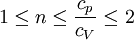
where k is constant, and n is bounded by:
where cV is the specific heat capacity at constant volume (J/kgK)
and cp is the specific heat capacity at constant pressure (J/kgK) Compared to the ideal cycle, the efficiency of a real engine is reduced by irreversibilities, friction, and the loss of short-circuit conducted heat, so that the overall efficiency is often only about half of the ideal (Carnot) efficiency. [12] Advantages of Stirling engines
Disadvantages of Stirling enginesSize and Cost Issues
Power and torque issues
Gas Choice Issues
Applications
Combined heat and power applicationsCombined heat and power (CHP) is an economical source of mechanical or electrical power, which uses a heat source in conjunction with a secondary heating application, usually a pre-existing energy use, such as an industrial process. Usually the primary heat source will enter the Stirling engine heater, since that will usually be at a higher temperature than the heating application, and the "waste" heat from the engine's heater will supply the secondary heating application. The power produced by the engine is often used to run an industrial or agricultural process, which in turn creates biomass waste refuse that can be used as free fuel for the engine, thus reducing waste removal costs. The overall process is very resourceful, thus making it efficient and cost-effective overall. WhisperGen, a New Zealand firm with offices in Christchurch, has developed an "AC Micro Combined Heat and Power" Stirling cycle engine. These microCHP units are gas-fired central heating boilers which sell power back into the electricity grid. WhisperGen announced in 2004 that they were producing 80,000 units for the residential market in the United Kingdom. A 20 unit trial in Germany started in 2006. Solar power generationPlaced at the focus of a parabolic mirror a Stirling engine can convert solar energy to electricity with an efficiency better than non-concentrated photovoltaic cells, and comparable to Concentrated Photo Voltaics. On August 11 2005, Southern California Edison announced [15] an agreement to purchase solar powered Stirling engines from Stirling Energy Systems [16] over a twenty year period and in quantity (20,000 units) sufficient to generate 500 megawatts of electricity. These systems, on a 4,500 acre (19 km²) solar farm, will use mirrors to direct and concentrate sunlight onto the engines which will in turn drive generators. Stirling cryocoolersAny Stirling engine will also work in reverse as a heat pump: i.e. when a motion is applied to the shaft, a temperature difference appears between the reservoirs. One of their modern uses is in refrigeration and cryogenics. The essential mechanical components of a Stirling cryocooler are identical to a Stirling engine. The turning of the shaft will compress the working gas causing its temperature to rise. This heat will then be dissipated by pushing the gas against a heat exchanger. Heat would then flow from the gas into this heat exchanger which would probably be cooled by passing a flow of air or other fluid over its exterior. The further turning of the shaft will then expand the working gas. Since it had just been cooled the expansion will reduce its temperature even further. The now very cold gas will be pushed against the other heat exchanger and heat would flow from it into the gas. The external side of this heat exchanger would be inside a thermally insulated compartment such as a refrigerator. This cycle would be repeated once for each turn of the shaft. Heat is in effect pumped out of this compartment, through the working gas of the cryocooler and dumped into the environment. The temperature inside the compartment will drop because its insulation prevents ambient heat from coming in to replace that pumped out. As with the Stirling engine, efficiency is improved by passing the gas through a “Regenerator” which buffers the flow of heat between the hot and cold ends of the gas chamber. The first Stirling-cycle cryocooler was developed at Philips in the 1950s and commercialized in such places as liquid nitrogen production plants. The Philips Cryogenics business evolved until it was split off in 1990 to form the Stirling Cryogenics & Refrigeration BV [17], The Netherlands. This company is still active in the development and manufacturing of Stirling cryocoolers and cryogenic cooling systems. A wide variety of smaller size Stirling cryocoolers are commercially available for tasks such as the cooling of sensors. Thermoacoustic refrigeration uses a Stirling cycle in a working gas which is created by high amplitude sound waves. Heat pumpA Stirling heat pump is very similar to a Stirling cryocooler, the main difference being that it usually operates at room-temperature and its principal application to date is to pump heat from the outside of a building to the inside, thus cheaply heating it. As with any other Stirling device, heat flows from the expansion space to the compression space; however, in contrast to the Stirling engine, the expansion space is at a lower temperature than the compression space, so instead of producing work, an input of mechanical work is required by the system (in order to satisfy the second law of thermodynamics). When the mechanical work for the heat-pump is provided by a second Stirling engine, then the overall system is called a "heat-driven, heat-pump". The expansion-side of the heat-pump is thermally coupled to the heat-source, which is often the external environment. The compression side of the Stirling device is placed in the environment to be heated, for example a building, and heat is "pumped" into it. Typically there will be thermal insulation between the two sides so there will be a temperature rise inside the insulated space. Heat-pumps are by far the most energy-efficient types of heating systems. Stirling heat-pumps also often have a higher coefficient of performance than conventional heat-pumps. To date, these systems have seen limited commercial use; however, use is expected to increase along with market demand for energy conservation, and adoption will likely be accelerated by technological refinements. Marine enginesKockums [18], the Swedish shipbuilder, had built at least 8 commercially successful Stirling powered submarines during the 1980s. As of 2005 they have started to carry compressed oxygen with them (see Gotland class submarine). Nuclear powerThere is a potential for nuclear-powered Stirling engines in electric power generation plants. Replacing the steam turbines of nuclear power plants with Stirling engines might simplify the plant, yield greater efficiency, and reduce the radioactive by-products. A number of breeder reactor designs use liquid sodium as coolant. If the heat is to be employed in a steam plant, a water/sodium heat exchanger is required, which raises some concern as sodium reacts violently with water. A Stirling engine obviates the need for water anywhere in the cycle. United States government labs have developed a modern Stirling engine design known as the Stirling Radioisotope Generator for use in space exploration. It is designed to generate electricity for deep space probes on missions lasting decades. The engine uses a single displacer to reduce moving parts and uses high energy acoustics to transfer energy. The heat source is a dry solid nuclear fuel slug and the heat sink is space itself. Automotive enginesIt is often claimed that the Stirling engine has too low a power/weight ratio and too long a starting time for automotive applications. There have been at least two automobiles exclusively powered by Stirling engines that were developed by NASA, as well as earlier projects by Ford and American Motor Companies. The main difficulties involved in using the Stirling engine in an automotive application are start-up time, acceleration response, shut-down time, and weight, not all of which have ready-made solutions. Many people believe that hybrid electric drive systems can bypass all of these setbacks. In November 2007, a prototype hybrid car using solid bio-fuel and a stirling engine was announced by the Precer project in Sweden. www.precer.se (in Swedish, with an English specification sheet under the PDF link). The NASA vehicles were designed by contractors and designated MOD I and MOD II. The MOD II replaced the normal spark-ignition engine in a 1985 4-door Chevrolet Celebrity hatchback. In the 1986 MOD II Design Report (Appendix A) the results show that the highway gas mileage was increased from 40 to 58 mpg and the urban mileage from 26 to 33 mpg with no change in gross weight of the vehicle. Start-up time in the NASA vehicle maxed out at 30 seconds, while Ford's research vehicle used an electric heater placed directly into the hot air mix to get the vehicle started in only a few seconds. Aircraft enginesStirling engines hold theoretical promise as aircraft engines. They are quieter, less polluting, gain efficiency with altitude, are more reliable due to fewer parts and the absence of an ignition system, produce much less vibration (airframes last longer) and safer, less explosive fuels may be used. (see below "Argument on why the Stirling engine can be applied in aviation" or "Why Aviation Needs the Stirling Engine" by Darryl Phillips, a 4-part series in the March 1993 to March 1994 issues of Stirling Machine World) Geothermal energySome believe that the ability of the Stirling engine to convert geothermal energy to electricity and then to hydrogen may well hold the key to replacement of fossil fuels in a future hydrogen economy. [19] This belief was also founded on research conducted at Los Alamos Labs that began as a hot dry rocks research, but later calculated the near limitless energy potential from molten rock on one side of a Stirling engine and ocean water on the other. Although currently the most feasible source of commercial electrical generation is solar, very long range predictions show advances in deep drilling and development of methods to work with molten rock could yield exponential levels of clean energy generation for thousands of years. Low temperature difference enginesA low temperature difference (Low Delta T, or LTD) Stirling engine will run on any low temperature differential, for example the difference between the palm of a hand and room-temperature or room temperature and an ice cube. Usually they are designed in a gamma configuration, for simplicity, and without a regenerator. They are typically unpressurized, running at near-atmospheric pressure. The power produced is less than one watt, and they are intended for demonstration purposes only. They are sold as toys and educational models. References
Academic References and Non-commercial Research
Academic Computer Tools
Further reading
Commercial manufacturers and suppliers
Categories: Cryogenics | Heat pumps | Hot air engines |
||||||||||||||||||||||||||||||||||||||||||||
| This article is licensed under the GNU Free Documentation License. It uses material from the Wikipedia article "Stirling_engine". A list of authors is available in Wikipedia. | ||||||||||||||||||||||||||||||||||||||||||||


 ,
,  .
. 

