To use all functions of this page, please activate cookies in your browser.
My watch list
my.chemeurope.com
my.chemeurope.com
With an accout for my.chemeurope.com you can always see everything at a glance – and you can configure your own website and individual newsletter.
- My watch list
- My saved searches
- My saved topics
- My newsletter
Orifice plate
An orifice plate is a device used to measure the rate of fluid flow. It uses the same principle as a Venturi nozzle, namely Bernoulli's principle which says that there is a relationship between the pressure of the fluid and the velocity of the fluid. When the velocity increases, the pressure decreases and vice versa. An orifice plate is basically a thin plate with a hole in the middle. It is usually placed in a pipe in which fluid flows. As fluid flows through the pipe, it has a certain velocity and a certain pressure. When the fluid reaches the orifice plate, with the hole in the middle, the fluid is forced to converge to go through the small hole; the point of maximum convergence actually occurs shortly downstream of the physical orifice, at the so-called vena contracta point (see drawing to the right). As it does so, the velocity and the pressure changes. Beyond the vena contracta, the fluid expands and the velocity and pressure change once again. By measuring the difference in fluid pressure between the normal pipe section and at the vena contracta, the volumetric and mass flow rates can be obtained from Bernoulli's equation. Product highlight
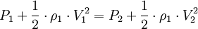
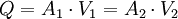
Flow of incompressible or compressible fluids through an orificeBy assuming steady-state, incompressible (constant fluid density), inviscid, laminar flow in a horizontal pipe (no change in elevation) with negligible frictional losses, Bernoulli's equation reduces to an equation relating the conservation of energy at two points in the fluid flow:
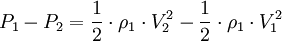
or:
with:
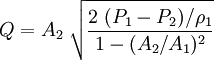
Solving for Q:
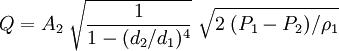
and:
and introducing the beta factor β = d2 / d1 as well as the coefficient of discharge Cd:
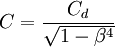
And finally introducing the expansion factor Y to account for the compressibility of gases and the meter coefficient C which is defined as
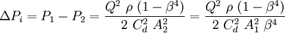
Multiplying by the density upstream of the orifice to obtain the equation for the mass flow of the fluid (either compressible or incompressible) at any point in the fluid flow:[1][2][3][4]
Deriving the above equations used the cross-section of the orifice opening and is not as realistic as using the minimum cross-section at the vena contracta. In addition, frictional losses may not be negligible and viscosity and turbulence effects may be present. For that reason, the coefficient of discharge Cd is introduced. Methods exist for determining the coefficient of discharge as a function of the Reynolds number.[2] The parameter The expansion factor, Y, accounts for the compressibility of gases. It is 1.0 for incompressible fluids and it can be calculated for compressible gases.[2] An orifice only works well when supplied with a fully developed flow profile. This is achieved by a long upstream length (20 to 40 pipe diameters, depending on Reynolds number) or the use of a flow conditioner. Orifice plates are small and inexpensive but do not recover the pressure drop as well as a venturi nozzle does. If space permits, a venturi meter is more efficient than a flowmeter. Flow of gases through an orificeThe expansion factor Y, which allows for the change in the density of an ideal gas as it expands adiabatically, is given by:[2]
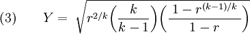
For values of β less than 0.25, β4 approaches 0 and the last bracketed term in the above equation approaches 1. Thus, for the large majority of orifice plate installations:
Substituting equation (3) into the mass flow rate equation (2):
and:
and thus, the final equation for the non-choked (i.e., sub-sonic) flow of real gases through an orifice:
Using the ideal gas law and the compressibility factor (which corrects for non-ideal gases), the equivalent equation is obtained for the non-choked flow of real gases through an orifice:[3][4][5]
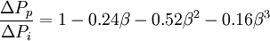
A detailed explanation of choked and non-choked flow of gases, as well as the equation for the choked flow of gases through restriction orifices, is available at Choked flow. The flow of real gases through thin-plate orifices never becomes fully choked. The mass flow rate through the orifice continues to increase as the downstream pressure is lowered to a perfect vacuum, though the mass flow rate increases slowly as the downstream pressure is reduced below the critical pressure.[6] "Cunningham (1951) first drew attention to the fact that choked flow will not occur across a standard, thin, square-edged orifice."[7] Permanent pressure drop for incompressible fluidsFor a square-edge orifice plate with flange taps[8]: where:
And rearranging the formula near the top of this article: See also
References
Categories: Fluid dynamics | Chemical engineering |
|||||||||||||||||||||||||||||||||||||||||||||||||||||||||||||||||
| This article is licensed under the GNU Free Documentation License. It uses material from the Wikipedia article "Orifice_plate". A list of authors is available in Wikipedia. |


 or
or 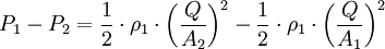
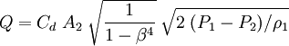
 to obtain the final equation for the volumetric flow of the fluid (either compressible or incompressible) upstream of the orifice:


 is often referred to as the velocity of approach factor
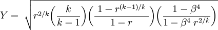
}](images/math/5/b/b/5bbadc21368c3510e8eb3b2dd3efa328.png)
}](images/math/e/b/9/eb98a07613c583dcf396fdec180c2d96.png)
![(4)\qquad \dot{m} = C\;A_2\;\sqrt{2\;\rho_1\;P_1\;\bigg (\frac{k}{k-1}\bigg)\bigg[(P_2/P_1)^{2/k}-(P_2/P_1)^{(k+1)/k}\bigg]}](images/math/7/d/8/7d849357b2b1d568bebc7b5fa0ce6674.png)
![(5)\qquad \dot{m} = C\;A_2\;P_1\;\sqrt{\frac{2\;M}{Z\;R\;T_1}\bigg(\frac{k}{k-1}\bigg)\bigg[(P_2/P_1)^{2/k}-(P_2/P_1)^{(k+1)/k}\bigg]}](images/math/d/f/4/df47869d1c0e15f9227045e8ac1e5f15.png)