To use all functions of this page, please activate cookies in your browser.
My watch list
my.chemeurope.com
my.chemeurope.com
With an accout for my.chemeurope.com you can always see everything at a glance – and you can configure your own website and individual newsletter.
- My watch list
- My saved searches
- My saved topics
- My newsletter
Polarization
Product highlight
TheoryBasics: plane wavesThe simplest manifestation of polarization to visualize is that of a plane wave, which is a good approximation of most light waves (a plane wave is a wave with infinitely long and wide wavefronts). All electromagnetic waves propagating in free space or in a uniform material of infinite extent have electric and magnetic fields perpendicular to the direction of propagation. Conventionally, when considering polarization, the electric field vector is described and the magnetic field is ignored since it is perpendicular to the electric field and proportional to it. The electric field vector may be arbitrarily divided into two perpendicular components labeled x and y (with z indicating the direction of travel). For a simple harmonic wave, where the amplitude of the electric vector varies in a sinusoidal manner, the two components have exactly the same frequency. However, these components have two other defining characteristics that can differ. First, the two components may not have the same amplitude. Second, the two components may not have the same phase, that is they may not reach their maxima and minima at the same time. The shape traced out in a fixed plane by the electric vector as such a plane wave passes over it (a Lissajous figure) is a description of the polarization state. The following figures show some examples of the evolution of the electric field vector (blue) with time (the vertical axes), along with its x and y components (red/left and green/right), and the path traced by the tip of the vector in the plane (purple):
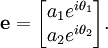
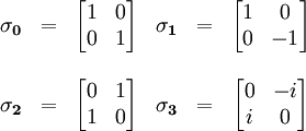
In the leftmost figure above, the two orthogonal (perpendicular) components are in phase. In this case the ratio of the strengths of the two components is constant, so the direction of the electric vector (the vector sum of these two components) is constant. Since the tip of the vector traces out a single line in the plane, this special case is called linear polarization. The direction of this line depends on the relative amplitudes of the two components. In the middle figure, the two orthogonal components have exactly the same amplitude and are exactly ninety degrees out of phase. In this case one component is zero when the other component is at maximum or minimum amplitude. There are two possible phase relationships that satisfy this requirement: the x component can be ninety degrees ahead of the y component or it can be ninety degrees behind the y component. In this special case the electric vector traces out a circle in the plane, so this special case is called circular polarization. The direction the field rotates in depends on which of the two phase relationships exists. These cases are called right-hand circular polarization and left-hand circular polarization, depending on which way the electric vector rotates. All other cases, that is where the two components are not in phase and either do not have the same amplitude and/or are not ninety degrees out of phase are called elliptical polarization because the electric vector traces out an ellipse in the plane (the polarization ellipse). The "Cartesian" decomposition of the electric field into x and y components is, of course, arbitrary. Plane waves of any polarization can be described instead by combining waves of opposite circular polarization, for example. The Cartesian polarization decomposition is natural when dealing with reflection from surfaces, birefringent materials, or synchrotron radiation. The circularly polarized modes are a more useful basis for the study of light propagation in stereoisomers. Incoherent radiationIn nature, electromagnetic radiation is often produced by a large number of individual sources, producing waves independently of each other. This type of light is described as incoherent. In general there is no single frequency but rather a spectrum of different frequencies present, and even if filtered to an arbitrarily narrow frequency range, there may not be a consistent state of polarization. However, this does not mean that polarization is only a feature of coherent radiation. Incoherent radiation may show statistical correlation between the components of the electric field, which can be interpreted as partial polarization. In general it is possible to describe an observed wave field as the sum of a completely incoherent part (no correlations) and a completely polarized part. One may then describe the light in terms of the degree of polarization, and the parameters of the polarization ellipse. Parameterizing polarizationFor ease of visualization, polarization states are often specified in terms of the polarization ellipse, specifically its orientation and elongation. A common parameterization uses the azimuth angle, ψ (the angle between the major semi-axis of the ellipse and the x-axis) and the ellipticity, ε (the ratio of the two semi-axes). An ellipticity of zero corresponds to linear polarization and an ellipticity of 1 corresponds to circular polarization. The arctangent of the ellipticity, χ = arctan ε (the "ellipticity angle"), is also commonly used. An example is shown in the diagram to the right. An alternative to the ellipticity or ellipticity angle is the eccentricity, however unlike the azimuth angle and ellipticity angle, the latter has no obvious geometrical interpretation in terms of the Poincaré sphere (see below). Full information on a completely polarized state is also provided by the amplitude and phase of oscillations in two components of the electric field vector in the plane of polarization. This representation was used above to show how different states of polarization are possible. The amplitude and phase information can be conveniently represented as a two-dimensional complex vector (the Jones vector): Here a1 and a2 denote the amplitude of the wave in the two components of the electric field vector, while θ1 and θ2 represent the phases. The product of a Jones vector with a complex number of unit modulus gives a different Jones vector representing the same ellipse, and thus the same state of polarization. The physical electric field, as the real part of the Jones vector, would be altered but the polarization state itself is independent of absolute phase. The basis vectors used to represent the Jones vector need not represent linear polarization states (i.e. be real). In general any two orthogonal states can be used, where an orthogonal vector pair is formally defined as one having a zero inner product. A common choice is left and right circular polarizations, for example to model the different propagation of waves in two such components in circularly birefringent media (see below) or signal paths of coherent detectors sensitive to circular polarization.
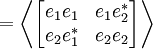
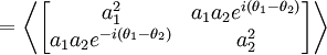
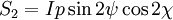
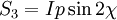
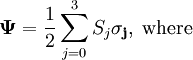
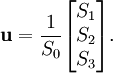
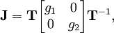
Regardless of whether polarization ellipses are represented using geometric parameters or Jones vectors, implicit in the parameterization is the orientation of the coordinate frame. This permits a degree of freedom, namely rotation about the propagation direction. When considering light that is propagating parallel to the surface of the Earth, the terms "horizontal" and "vertical" polarization are often used, with the former being associated with the first component of the Jones vector, or zero azimuth angle. On the other hand, in astronomy the equatorial coordinate system is generally used instead, with the zero azimuth (or position angle, as it is more commonly called in astronomy to avoid confusion with the horizontal coordinate system) corresponding to due north. Another coordinate system frequently used relates to the plane made by the propagation direction and a vector normal to the plane of a reflecting surface. This is known as the plane of incidence. The rays in this plane are illustrated in the diagram to the right. The component of the electric field parallel to this plane is termed p-like (parallel) and the component perpendicular to this plane is termed s-like (from senkrecht, German for perpendicular). Light with a p-like electric field is said to be p-polarized, pi-polarized, tangential plane polarized, or is said to be a transverse-magnetic (TM) wave. Light with an s-like electric field is s-polarized, also known as sigma-polarized or sagittal plane polarized, or it can be called a transverse-electric (TE) wave. In the case of partially-polarized radiation, the Jones vector varies in time and space in a way that differs from the constant rate of phase rotation of monochromatic, purely-polarized waves. In this case, the wave field is likely stochastic, and only statistical information can be gathered about the variations and correlations between components of the electric field. This information is embodied in the coherency matrix: where angular brackets denote averaging over many wave cycles. Several variants of the coherency matrix have been proposed: the Wiener coherency matrix and the spectral coherency matrix of Richard Barakat measure the coherence of a spectral decomposition of the signal, while the Wolf coherency matrix averages over all time/frequencies. The coherency matrix contains all of the information on polarization that is obtainable using second order statistics. It can be decomposed into the sum of two idempotent matrices, corresponding to the eigenvectors of the coherency matrix, each representing a polarization state that is orthogonal to the other. An alternative decomposition is into completely polarized (zero determinant) and unpolarized (scaled identity matrix) components. In either case, the operation of summing the components corresponds to the incoherent superposition of waves from the two components. The latter case gives rise to the concept of the "degree of polarization"; i.e., the fraction of the total intensity contributed by the completely polarized component. The coherency matrix is not easy to visualize, and it is therefore common to describe incoherent or partially polarized radiation in terms of its total intensity (I), (fractional) degree of polarization (p), and the shape parameters of the polarization ellipse. An alternative and mathematically convenient description is given by the Stokes parameters, introduced by George Gabriel Stokes in 1852. The relationship of the Stokes parameters to intensity and polarization ellipse parameters is shown in the equations and figure below. Here Ip, 2ψ and 2χ are the spherical coordinates of the polarization state in the three-dimensional space of the last three Stokes parameters. Note the factors of two before ψ and χ corresponding respectively to the facts that any polarization ellipse is indistinguishable from one rotated by 180°, or one with the semi-axis lengths swapped accompanied by a 90° rotation. The Stokes parameters are sometimes denoted I, Q, U and V. The Stokes parameters contain all of the information of the coherency matrix, and are related to it linearly by means of the identity matrix plus the three Pauli matrices: Mathematically, the factor of two relating physical angles to their counterparts in Stokes space derives from the use of second-order moments and correlations, and incorporates the loss of information due to absolute phase invariance. The figure above makes use of a convenient representation of the last three Stokes parameters as components in a three-dimensional vector space. This space is closely related to the Poincaré sphere, which is the spherical surface occupied by completely polarized states in the space of the vector All four Stokes parameters can also be combined into the four-dimensional Stokes vector, which can be interpreted as four-vectors of Minkowski space. In this case, all physically realizable polarization states correspond to time-like, future-directed vectors. Propagation, reflection and scatteringIn a vacuum, the components of the electric field propagate at the speed of light, so that the phase of the wave varies in space in time while the polarization state does not. That is, where k is the wavenumber and positive z is the direction of propagation. As noted above, the physical electric vector is the real part of the Jones vector. When electromagnetic waves interact with matter, their propagation is altered. If this depends on the polarization states of the waves, then their polarization may also be altered. In many types of media, electromagnetic waves may be decomposed into two orthogonal components that encounter different propagation effects. A similar situation occurs in the signal processing paths of detection systems that record the electric field directly. Such effects are most easily characterized in the form of a complex 2×2 transformation matrix called the Jones matrix: In general the Jones matrix of a medium depends on the frequency of the waves. For propagation effects in two orthogonal modes, the Jones matrix can be written as where g1 and g2 are complex numbers representing the change in amplitude and phase caused in each of the two propagation modes, and T is a unitary matrix representing a change of basis from these propagation modes to the linear system used for the Jones vectors. For those media in which the amplitudes are unchanged but a differential phase delay occurs, the Jones matrix is unitary, while those affecting amplitude without phase have Hermitian Jones matrices. In fact, since any matrix may be written as the product of unitary and positive Hermitian matrices, any sequence of linear propagation effects, no matter how complex, can be written as the product of these two basic types of transformations. Paths taken by vectors in the Poincaré sphere under birefringence. The propagation modes (rotation axes) are shown with red, blue, and yellow lines, the initial vectors by thick black lines, and the paths they take by colored ellipses (which represent circles in three dimensions). Media in which the two modes accrue a differential delay are called birefringent. Well known manifestations of this effect appear in optical wave plates/retarders (linear modes) and in Faraday rotation/optical rotation (circular modes). An easily visualized example is one where the propagation modes are linear, and the incoming radiation is linearly polarized at a 45° angle to the modes. As the phase difference starts to appear, the polarization becomes elliptical, eventually changing to purely circular polarization (90° phase difference), then to elliptical and eventually linear polarization (180° phase) with an azimuth angle perpendicular to the original direction, then through circular again (270° phase), then elliptical with the original azimuth angle, and finally back to the original linearly polarized state (360° phase) where the cycle begins anew. In general the situation is more complicated and can be characterized as a rotation in the Poincaré sphere about the axis defined by the propagation modes (this is a consequence of the isomorphism of SU(2) with SO(3)). Examples for linear (blue), circular (red), and elliptical (yellow) birefringence are shown in the figure on the left. The total intensity and degree of polarization are unaffected. If the path length in the birefringent medium is sufficient, plane waves will exit the material with a significantly different propagation direction, due to refraction. For example, this is the case with macroscopic crystals of calcite, which present the viewer with two offset, orthogonally polarized images of whatever is viewed through them. It was this effect that provided the first discovery of polarization, by Erasmus Bartholinus in 1669. In addition, the phase shift, and thus the change in polarization state, is usually frequency dependent, which, in combination with dichroism, often gives rise to bright colors and rainbow-like effects. Media in which the amplitude of waves propagating in one of the modes is reduced are called dichroic. Devices that block nearly all of the radiation in one mode are known as polarizing filters or simply "polarizers". In terms of the Stokes parameters, the total intensity is reduced while vectors in the Poincaré sphere are "dragged" towards the direction of the favored mode. Mathematically, under the treatment of the Stokes parameters as a Minkowski 4-vector, the transformation is a scaled Lorentz boost (due to the isomorphism of SL(2,C) and the restricted Lorentz group, SO(3,1)). Just as the Lorentz transformation preserves the proper time, the quantity det Ψ = S02-S12-S22-S32 is invariant within a multiplicative scalar constant under Jones matrix transformations (dichroic and/or birefringent). In birefringent and dichroic media, in addition to writing a Jones matrix for the net effect of passing through a particular path in a given medium, the evolution of the polarization state along that path can be characterized as the (matrix) product of an infinite series of infinitesimal steps, each operating on the state produced by all earlier matrices. In a uniform medium each step is the same, and one may write where J is an overall (real) gain/loss factor. Here D is a traceless matrix such that αDe gives the derivative of e with respect to z. If D is Hermitian the effect is dichroism, while a unitary matrix models birefringence. The matrix D can be expressed as a linear combination of the Pauli matrices, where real coefficients give Hermitian matrices and imaginary coefficients give unitary matrices. The Jones matrix in each case may therefore be written with the convenient construction where σ is a 3-vector composed of the Pauli matrices (used here as generators for the Lie group SL(2,C)) and n and m are real 3-vectors on the Poincaré sphere corresponding to one of the propagation modes of the medium. The effects in that space correspond to a Lorentz boost of velocity parameter 2β along the given direction, or a rotation of angle 2φ about the given axis. These transformations may also be written as biquaternions (quaternions with complex elements), where the elements are related to the Jones matrix in the same way that the Stokes parameters are related to the coherency matrix. They may then be applied in pre- and post-multiplication to the quaternion representation of the coherency matrix, with the usual exploitation of the quaternion exponential for performing rotations and boosts taking a form equivalent to the matrix exponential equations above. (See Quaternion rotation) In addition to birefringence and dichroism in extended media, polarization effects describable using Jones matrices can also occur at (reflective) interface between two materials of different refractive index. These effects are treated by the Fresnel equations. Part of the wave is transmitted and part is reflected, with the ratio depending on angle of incidence and the angle of refraction. In addition, if the plane of the reflecting surface is not aligned with the plane of propagation of the wave, the polarization of the two parts is altered. In general, the Jones matrices of the reflection and transmission are real and diagonal, making the effect similar to that of a simple linear polarizer. For unpolarized light striking a surface at a certain optimum angle of incidence known as Brewster's angle, the reflected wave will be completely s-polarized. Certain effects do not produce linear transformations of the Jones vector, and thus cannot be described with (constant) Jones matrices. For these cases it is usual instead to use a 4×4 matrix that acts upon the Stokes 4-vector. Such matrices were first used by Paul Soleillet in 1929, although they have come to be known as Mueller matrices. While every Jones matrix has a Mueller matrix, the reverse is not true. Mueller matrices are frequently used to study the effects of the scattering of waves from complex surfaces or ensembles of particles. Polarization in nature, science, and technologyPolarization effects in everyday lifeLight reflected by shiny transparent materials is partly or fully polarized, except when the light is normal (perpendicular) to the surface. A polarizing filter, such as a pair of polarizing sunglasses, can be used to observe this by rotating the filter while looking through. At certain angles, the reflected light will be reduced or eliminated. Polarizing filters remove light polarized at 90° to the filter's polarization axis. If two polarizers are placed atop one another at 90° angles to one another, there is minimal light transmission. Polarization by scattering is observed as light passes through the atmosphere. The scattered light produces the brightness and color in clear skies. This partial polarization of scattered light can be used to darken the sky in photographs, increasing the contrast. This effect is easiest to observe at sunset, on the horizon at a 90° angle from the setting sun. Another easily observed effect is the drastic reduction in brightness of images of the sky and clouds reflected from horizontal surfaces, which is the main reason polarizing filters are often used in sunglasses. Also frequently visible through polarizing sunglasses are rainbow-like patterns caused by color-dependent birefringent effects, for example in toughened glass (e.g. car windows) or items made from transparent plastics. The role played by polarization in the operation of liquid crystal displays (LCD's) is also frequently apparent to the wearer of polarizing sunglasses, which may reduce the contrast or even make the display unreadable. The photograph on the right was taken through polarizing sunglasses and through the rear window of a car. Light from the sky is reflected by the windshield of the other car at an angle, making it mostly horizontally polarized. The rear window is made of tempered glass. Stress in the glass, left from its heat treatment, causes it to alter the polarization of light passing through it, like a wave plate. Without this effect, the sunglasses would block the horizontally polarized light reflected from the other car's window. The stress in the rear window, however, changes some of the horizontally polarized light into vertically polarized light that can pass through the glasses. As a result, the regular pattern of the heat treatment becomes visible. BiologyMany animals are apparently capable of perceiving the polarization of light, which is generally used for navigational purposes, since the linear polarization of sky light is always perpendicular to the direction of the sun. This ability is very common among the insects, including bees, which use this information to orient their communicative dances. Polarization sensitivity has also been observed in species of octopus, squid, cuttlefish, and mantis shrimp. The rapidly changing, vividly colored skin patterns of cuttlefish, used for communication, also incorporate polarization patterns, and mantis shrimp are known to have polarization selective reflective tissue. Sky polarization was thought to be perceived by pigeons, which was assumed to be one of their aids in homing, but research indicates this is a popular myth.[1] The naked human eye is weakly sensitive to polarization, without the need for intervening filters. Polarized light creates a very faint pattern near the center of the visual field, called Haidinger's brush. This pattern is very difficult to see, but with practice one can learn to detect polarized light with the naked eye. GeologyThe property of (linear) birefringence is widespread in crystalline minerals, and indeed was pivotal in the initial discovery of polarization. In mineralogy, this property is frequently exploited using polarization microscopes, for the purpose of identifying minerals. See pleochroism. ChemistryPolarization is principally of importance in chemistry due to the circular dichroism and "optical rotation" (circular birefringence) exhibited by optically active (chiral) molecules. It may be measured using a polarimeter. Polarization may also refer to the through-bond (inductive or resonant effect) or through-space influence of a nearby functional group on the electronic properties (e.g. dipole moment) of a covalent bond or atom. AstronomyIn many areas of astronomy, the study of polarized electromagnetic radiation from outer space is of great importance. Although not usually a factor in the thermal radiation of stars, polarization is also present in radiation from coherent astronomical sources (e.g. hydroxyl or methanol masers), and incoherent sources such as the large radio lobes in active galaxies, and pulsar radio radiation (which may, it is speculated, sometimes be coherent), and is also imposed upon starlight by scattering from interstellar dust. Apart from providing information on sources of radiation and scattering, polarization also probes the interstellar magnetic field via Faraday rotation. The polarization of the cosmic microwave background is being used to study the physics of the very early universe. Synchrotron radiation is inherently polarised. TechnologyTechnological applications of polarization are extremely widespread. Perhaps the most commonly encountered examples are liquid crystal displays and polarized sunglasses. All radio transmitting and receiving antennas are intrinsically polarized, special use of which is made in radar. Most antennas radiate either horizontal, vertical, or circular polarization although elliptical polarization also exists. The electric field or E-plane determines the polarization or orientation of the radio wave. Vertical polarization is most often used when it is desired to radiate a radio signal in all directions such as widely distributed mobile units. AM and FM radio uses vertical polarization. Television uses horizontal polarization. Alternating vertical and horizontal polarization is used on satellite communications (including television satellites), to reduce interference between programs on the same frequency band transmitted from adjacent satellites (one uses vertical, the next horizontal, and so on), allowing for reduced angular separation between the satellites. In engineering, the relationship between strain and birefringence motivates the use of polarization in characterizing the distribution of stress and strain in prototypes. Electronically controlled birefringent devices are used in combination with polarizing filters as modulators in fiber optics. Polarizing filters are also used in photography. They can deepen the color of a blue sky and eliminate reflections from windows and standing water. Sky polarization has been exploited in the "sky compass", which was used in the 1950s when navigating near the poles of the Earth's magnetic field when neither the sun nor stars were visible (e.g. under daytime cloud or twilight). It has been suggested, controversially, that the Vikings exploited a similar device (the "sunstone") in their extensive expeditions across the North Atlantic in the 9th–11th centuries, before the arrival of the magnetic compass in Europe in the 12th century. Related to the sky compass is the "polar clock", invented by Charles Wheatstone in the late 19th century. Polarization is also used for some 3D movies, in which the images intended for each eye are either projected from two different projectors with orthogonally oriented polarizing filters or from a single projector with time multiplexed polarization (a fast alternating polarization device for successive frames). Filter glasses with similarly oriented polarized filters ensure that each eye receives only the correct image. Typical stereoscopic projection displays use linear polarization encoding, because it is not very expensive and offers high contrast. In environments where the viewer is moving, such as in simulators, circular polarization is sometimes used. This makes the channel separation insensitive to the viewing orientation. The 3-D effect only works on a silver screen since it maintains polarization, whereas the scattering in a normal projection screen would void the effect. ArtSeveral visual artists have worked with polarized light and birefringent materials to create colorful, sometimes changing images. Most notable is contemporary artist Austine Wood Comarow, whose "Polage" art works have been exhibited at the Museum of Science, Boston, the New Mexico Museum of Natural History and Science in Albuquerque, NM, and la Cité des Sciences et de l'Industrie (the City of Science and Industry) in Paris. The artist works by cutting hundreds of small pieces of cellophane and other birefringent films and laminating them between plane polarizing filters. Other examples of polarization
See also
Notes and references
Categories: Polarization | Electromagnetic radiation |
|||||
| This article is licensed under the GNU Free Documentation License. It uses material from the Wikipedia article "Polarization". A list of authors is available in Wikipedia. |