To use all functions of this page, please activate cookies in your browser.
My watch list
my.chemeurope.com
my.chemeurope.com
With an accout for my.chemeurope.com you can always see everything at a glance – and you can configure your own website and individual newsletter.
- My watch list
- My saved searches
- My saved topics
- My newsletter
Lift (force)The lift force, lifting force or simply lift is a mechanical force generated by solid objects as they move through a fluid.[1] While many types of objects can generate lift, the most common and familiar object in this category is the airfoil, a relatively flat object of which the common airplane wing is an example. For the sake of simplicity, this article will discuss lift primarily in the context of airfoils and wings. Product highlight
OverviewTechnically, lift is the sum of all the fluid dynamic forces on a body perpendicular to the direction of the external flow approaching that body. The mathematical equations describing lift have been well established since the Wright Brothers experimentally determined a reasonably precise value for the "Smeaton coefficient" more than 100 years ago,[2] but the practical explanation of what those equations mean is still controversial, with persistent misinformation and pervasive misunderstanding.[3] Sometimes the term dynamic lift or dynamic lifting force is used for the perpendicular force resulting from motion of the body in the fluid, as in an aerodyne, in contrast to the static lifting force resulting from buoyancy, as in an aerostat. Lift is commonly associated with the wing of an aircraft. However there are many other examples of lift such as propellers on both aircraft and boats, rotors on helicopters, sails and keels on sailboats, hydrofoils, wings on auto racing cars, and wind turbines. While the common meaning of the term "lift" suggests an upward action, the lift force is not necessarily directed up with respect to gravity. Physical explanationLift is generated when an object turns a fluid away from its direction of flow. When the object and fluid move relative to each other, the object turns the fluid flow in a direction perpendicular to that flow, and the force required to do this creates an equal and opposite force that is lift. The object may be moving through a stationary fluid, or the fluid may be flowing past a stationary object— these two are effectively identical as, in principle, it is only the frame of reference of the viewer which differs. In the case of an aircraft wing, pressure regions turn the passing flow of air downward towards the ground. These pressure regions exert an equal and opposite force on the wing, called lift, that supports the aircraft in the air. The lift generated by an airfoil depends on such factors as the speed of the airflow, the density of the air, the total area of the airfoil, and the angle of attack. The angle of attack is the angle at which the airfoil meets the oncoming airflow (or vice versa). A symmetric airfoil must have a positive angle of attack to generate positive lift. At a zero angle of attack, no lift is generated. At a negative angle of attack, negative lift is generated. A cambered airfoil may produce positive lift at zero, or even small negative angles of attack. The basic concept of lift is simple. However, the details of how the relative movement of air and airfoil interact to produce the turning action that generates lift are complex. Below are several explanations of lift, all of which are different but equivalent descriptions of the same phenomenon from different viewpoints. Reaction due to deflectionLift is created as the fluid flow is deflected by an airfoil or other body. The force created by this acceleration of the fluid creates an equal and opposite force according to Newton's third law of motion. Air deflected downward by an aircraft wing, or helicopter rotor, generating lift is known as downwash. It is important to note that the acceleration of air flowing over an aircraft wing does not just involve the air molecules "bouncing off" the lower surface. Rather the air follows both the top and bottom surfaces and is deflected downward both above and below the wing. The acceleration of the air during the creation of lift can also be described as a "turning" of the airflow. Many shapes, such as a flat plate set at an angle to the flow, will produce lift. This can be demonstrated simply by holding a sheet of paper at an angle in front of you as you move forward, or holding your hand out of the car window. Without any assistance from you, the sheet of paper or your hand will rise in the air. However, lift generation by most shapes will be very inefficient and create a great deal of drag. One of the primary goals of airfoil design is to devise a shape that produces the most lift while producing the least form drag. It is possible to measure lift using the reaction model. The force acting on the wing is the negative of the time-rate-of-change of the momentum of the air. In a wind tunnel, the speed and direction of the air can be measured (using, for example, a Pitot tube or Laser Doppler velocimetry) and the lift calculated. Alternately, the force on the wind tunnel itself can be measured as the equal and opposite forces to those acting on the test object. Bernoulli's principleThe force on the wing can also be examined in terms of the pressure differences above and below the wing, which can be related to velocity changes by Bernoulli's principle. The total Lift force is the integral of vertical pressure forces over the entire wetted surface area of the wing:
where:
The above lift equation neglects the Skin friction forces, which typically have a negligible contribution to the lift compared to the pressure forces. By using the streamwise vector
The Bernoulli principle states that the sum total of energy within a parcel of fluid remains constant as long as no energy is added or removed. It is a statement of the principle of the conservation of energy applied to flowing fluids. A substantial simplification of this proposes that as other forms of energy changes are inconsequential during the flow of air around a wing and that energy transfer in/out of the air is not significant, then the sum of pressure energy and speed energy for any particular parcel of air must be constant. Consequently, an increase in speed must be accompanied by a decrease in pressure and vice-versa. It should be noted that this is not a causational relationship. Rather, it is a coincidental relationship, whatever causes one must also cause the other as energy can neither be created nor destroyed. It is named for the Dutch-Swiss mathematician and scientist Daniel Bernoulli, though it was previously understood by Leonhard Euler and others. Bernoulli's principle provides an explanation of pressure difference in the absence of air density and temperature variation (a common approximation for low-speed aircraft). If the air density and temperature are the same above and below a wing, a naive application of the ideal gas law requires that the pressure also be the same. Bernoulli's principle, by including air velocity, explains this pressure difference. The principle does not, however, specify the air velocity. This must come from another source, e.g., experimental data. Erroneous assumptions concerning velocity, e.g., that two parcels of air separated at the front of the wing must meet up again at the back of the wing, are commonly found. [4] In order to solve for the velocity of inviscid flow around a wing, the Kutta condition must be applied to simulate the effects of inertia and viscosity. The Kutta condition allows for the correct choice among an infinite number of flow solutions that otherwise obey the laws of conservation of mass and conservation of momentum. CirculationA third way to calculate lift is to determine the mathematical quantity called circulation; (this concept is sometimes applied approximately to wings of large aspect ratio as "lifting-line theory"). Again, it is mathematically equivalent to the two explanations above. It is often used by practicing aerodynamicists as a convenient quantity in calculations, see thin-airfoil theory for example. The circulation is the line integral of the velocity of the air, in a closed loop around the boundary of an airfoil. It can be understood as the total amount of "spinning" (or vorticity) of air around the airfoil. When the circulation is known, the section lift/span L' can be calculated using the following equation:
where ρ is the air density, V is the free-stream airspeed, and Γ is the circulation. This is sometimes known as the Kutta-Joukowski Theorem. A similar equation applies to the sideways force generated around a spinning object, the Magnus effect, though here the necessary circulation is induced by the mechanical rotation acting on the boundary layer, causing it to separate at different points between top and bottom. The asymmetric separation then produces a circulation in the outer inviscid flow. The Helmholtz theorem states that circulation is conserved; put simply this is conservation of the air's angular momentum. When an aircraft is at rest, there is no circulation. As the flow speed increases (that is, the aircraft accelerates in the air-body-fixed frame), a vortex, called the starting vortex, forms at the trailing edge of the airfoil, due to viscous effects in the boundary layer. Eventually the vortex detaches from the airfoil and gets swept away from it rearward. The circulation in the starting vortex is equal in magnitude and opposite in direction to the circulation around the airfoil. Theoretically, the starting vortex remains connected to the vortex bound in the airfoil, through the wing-tip vortices, forming a closed circuit. In reality, the starting vortex is dissipated by a number of effects, as are the wing-tip vortices far behind the aircraft. However, the net circulation in "the world" is still zero as the circulation from the vortices is transferred to the surroundings as they dissipate. (Note that despite being an idealisation of the real world, the 'vortex system' set up round a wing is both real and observable, and is one of the reasons that a light aircraft cannot take off immediately after a jumbo jet.) Common misconceptionsEqual transit-timeOne misconception encountered in a number of explanations of lift is the "equal transit time" fallacy. This fallacy states that the parcels of air which are divided by an airfoil must rejoin again; because of the greater curvature (and hence longer path) of the upper surface of an airfoil, the air going over the top must go faster in order to "catch up" with the air flowing around the bottom. Although it is true that the air moving over the top of the wing is moving faster (when the effective angle of attack is positive) there is no requirement for equal transit time. In fact if the air above and below an airfoil has equal transit time, there is no circulation, and therefore no lift. Only if the air flowing above has a shorter transit time than the air flowing below, is upward lift produced, along with downward deflection of the air behind the wing and a vortex at each wing tip. Wind tunnel smoke streamline pictures reveal these flow features.[5][6] A further flaw in this explanation is that it requires an airfoil to have a curvature in order to create lift. In fact, a thin, flat plate inclined to a flow of fluid also generates lift.[7][8] It is unclear why this explanation has gained such currency, except by repetition by authors of populist (rather than rigorously scientific) books and perhaps the fact that the explanation is easiest to grasp intuitively without mathematics. At least one common flight training book depicts the equal transit fallacy, adding to the confusion.[9] Albert Einstein, in attempting to design a practical aircraft based on this principle, came up with an airfoil section that featured a large hump on its upper surface, on the basis that an even longer path must aid lift if the principle is true. Its performance was terrible.[10]
Coanda effect
There are two techniques for increasing the lift on an airfoil. One is to decrease the pressure on the side of the airfoil normal to the direction of the desired lift and the other is to increase the pressure on the other side. (The former is the primary cause of the lift even for a paper airplane.) In order to generate lift one must create a pressure differential between the top and bottom of the airfoil. The Coandă effect is the name given to the tendency of an airflow, under some conditions, to deflect toward a surface that curves away from the flow direction. This effect is caused by the decreased pressure on the curved surface where it curves away from the flow. Jef Raskin and a few others have observed that the Coandă effect accounts for part of the lift generated by an airfoil. The decrease in pressure above the airfoil is caused by the interaction of the flow, at the microscopic level, with the curved surface. The effect is caused by a decrease of the pressure on the top of the wing as air particles are blown away from the surface (fewer particles, less pressure due to thermal molecular motion). This contributes to the pressure field under the integral sign in the lift equation. For large angles of attack and/or high flow rates the Coandă effect results in vortices which may impinge normally on the surface thus increasing the pressure there. Under these circumstances the wing will lose lift and ultimately stall. This aspect of the Coandă effect has been used successfully in the design of the wings in Formula One race cars to pressurize the back of the car and partially offset drag. Lift coefficientThe lift coefficient is a dimensionless number. When the lift coefficient is known, for instance from tables of airfoil data, lift can be calculated using the Lift Equation: where:
This equation can be used in any consistent system. For instance, if the density is measured in kilograms per cubic metre, the velocity is measured in metres per second, and the area is measured in square metres, the lift will be calculated in newtons. Or, if the density is in slugs per cubic foot, the velocity is in feet per second, and the area is in square feet, the resulting lift will be in pounds force. * Note that at altitudes other than sea level, the density can be found using the barometric formula Compare with: Drag equation. See also
References
Further reading
|
|||
| This article is licensed under the GNU Free Documentation License. It uses material from the Wikipedia article "Lift_(force)". A list of authors is available in Wikipedia. |


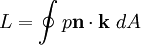
 is the normal unit vector pointing into the wing
 is the vertical unit vector, normal to the freestream direction
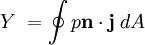
 parallel to the freestream in place of
  , we obtain the Sideforce
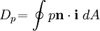
Last viewed


