To use all functions of this page, please activate cookies in your browser.
My watch list
my.chemeurope.com
my.chemeurope.com
With an accout for my.chemeurope.com you can always see everything at a glance – and you can configure your own website and individual newsletter.
- My watch list
- My saved searches
- My saved topics
- My newsletter
Fossil fuel power plant
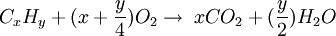
A fossil fuel power plant is an energy conversion center that burns fossil fuels to produce electricity, designed on a large scale for continuous operation. Product highlightBasic conceptsIn a fossil fuel power plant the chemical energy stored in fossil fuels such as coal, fuel oil, natural gas or oil shale is converted successively into thermal energy, mechanical energy and, finally, electrical energy for continuous use and distribution across a wide geographic area. Almost all large fossil fuel power plants are steam-electric power plants, except for gas turbines and utility-sized generators that may run on natural gas or diesel. The complete combustion of fossil fuel is summarized in the following chemical reaction: and the simple word equation for this chemical reaction is: All fossil fuels generate carbon dioxide when burned. Other products of incomplete combustion are sulfur dioxide (predominantly in coal) and oxides of nitrogen; since no fossil fuel power plant is able to burn the fuel perfectly as seen in complete combustion, such products are always produced in some quantity. Each fossil fuel power plant is a highly complex, custom-designed system. Present construction costs, as of 2004, run to US$1,300 per kilowatt, or $650 million for a 500 MW unit. Multiple generating units may be built at a single site for more efficient use of land, natural resources and labor. ^^Fuel transport and delivery^^ Coal is delivered by highway truck, rail, barge or collier ship. A large coal train called a "unit train" may be two kilometers (over a mile) long, containing 100 cars with 100 tons of coal in each one, for a total load of 10,000 tons. A large plant under full load requires at least one coal delivery this size every day. Plants may get as many as three to five trains a day, especially in "peak season", during the summer months when power consumption is high. A large thermal power plant such as the one in Nanticoke, Ontario stores several million tons of coal for winter use when the lakes are frozen. Modern unloaders use rotary dump devices, which eliminate problems with coal freezing in bottom dump cars. The unloader includes a train positioner arm that pulls the entire train to position each car over a coal hopper. The dumper clamps an individual car against a platform that swivels the car upside down to dump the coal. Swiveling couplers enable the entire operation to occur while the cars are still coupled together. Unloading a unit train takes about three hours. Shorter trains may use railcars with an "air-dump", which relies on air pressure from the engine plus a "hot shoe" on each car. This "hot shoe" when it comes into contact with a "hot rail" at the unloading trestle, shoots an electric charge through the air dump apparatus and causes the doors on the bottom of the car to open, dumping the coal through the opening in the trestle. Unloading one of these trains takes anywhere from an hour to an hour and a half. Older unloaders may still use manually operated bottom-dump rail cars and a "shaker" attached to dump the coal. Generating stations adjacent to a mine may receive coal by conveyor belt or massive diesel-electric-drive trucks. A collier (cargo ship carrying coal) may hold 40,000 tons of coal and takes several days to unload. Some colliers carry their own conveying equipment to unload their own bunkers; others depend on equipment at the plant. Colliers are large, seaworthy, self-powered ships. For transporting coal in calmer waters, such as rivers and lakes, flat-bottomed vessels called barges are often used. Barges are usually unpowered and must be moved by tugboats or towboats. For startup or auxiliary purposes, the plant may use fuel oil as well. Fuel oil can be delivered to plants by pipeline, tanker, tank car or truck. Oil is stored in vertical cylindrical steel tanks with capacities as high as 90,000 barrels' worth (14,000 m³, or about 5 million US gallons). The heavier no. 5 "bunker" and no. 6 fuels are typically steam-heated before pumping in cold climates. Plants fueled by natural gas are usually built adjacent to gas transport pipelines or have dedicated gas pipelines extended to them. |Fuel processing| Coal is prepared for use by crushing the rough coal to pieces less than 2 inches (50 mm) in size. The coal is then transported from the storage yard to in-plant storage silos by rubberized conveyor belts at rates up to 4,000 tons/hour. In plants that burn pulverized coal, silos feed coal pulverizers (coal mill) that take the larger 2 inch pieces grind them into the consistency of consistency of face powder, classify them, and mixes them with primary combustion air which transports the coal to the furnace and preheats the coal to drive off excess moisture content. A 500 MWe plant will have six such pulverizers, five of which can supply coal to the furnace at 250 tons per hour under full load. In plants that do not burn pulverized coal, the larger 2 inch pieces may be directly fed into the silos which then feed the cyclone burners, a specific kind of combustor that can efficiently burn larger pieces of fuel. Feedwater heating and deaerationThe feedwater used in the steam boiler is a means of transferring heat energy from the burning fuel to the mechanical energy of the spinning steam turbine. The total feedwater consists of recirculated condensate water and purified makeup water. Because the metallic materials it contacts are subject to corrosion at high temperatures and pressures, the makeup water is highly purified before use. A system of water softeners and ion exchange demineralizers produces water so pure that it coincidentally becomes an electrical insulator, with conductivity in the range of 0.3–1.0 microsiemens per centimeter. The makeup water in a 500 MWe plant amounts to perhaps 20 US gallons per minute (1.25 L/s) to offset the small losses from steam leaks in the system. The feedwater cycle begins with condensate water being pumped out of the condenser after traveling through the steam turbines. The condensate flow rate at full load in a 500 MWe plant is about 6,000 US gallons per minute (0.38 m³/s). The water flows through a series of six or seven intermediate feedwater heaters, heated up at each point with steam extracted from an appropriate duct on the turbines and gaining temperature at each stage. Typically, the condensate plus the makeup water then flows through a deaerator[1][2] that removes dissolved air from the water, further purifying and reducing its corrosivity. The water may be dosed following this point with hydrazine, a chemical that removes the remaining oxygen in the water to below 5 parts per billion (ppb). It is also dosed with pH control agents such as ammonia or morpholine to keep the residual acidity low and thus non-corrosive. Boiler operationThe boiler is a rectangular furnace about 50 ft (15 m) on a side and 130 ft (40 m) tall. Its walls are made of a web of high pressure steel tubes about 2.3 inches (60 mm) in diameter. Pulverized coal is air-blown into the furnace from fuel nozzles at the four corners and it rapidly burns, forming a large fireball at the center. The thermal radiation of the fireball heats the water that circulates through the boiler tubes near the boiler perimeter. The water circulation rate in the boiler is three to four times the throughput and is typically driven by pumps. As the water in the boiler circulates it absorbs heat and changes into steam at 700 °F (370 °C) and 3,200 psi (22.1 MPa). It is separated from the water inside a drum at the top of the furnace. The saturated steam is introduced into superheat pendant tubes that hang in the hottest part of the combustion gases as they exit the furnace. Here the steam is superheated to 1,000 °F (540 °C) to prepare it for the turbine. Plants designed for lignite (brown coal) are increasingly used in locations as varied as Germany, Victoria, and North Dakota. Lignite is a much younger form of coal than black coal. It has a lower energy density than black coal and requires a much larger furnace for equivalent heat output. Such coals may contain up to 70% water and ash, yielding lower furnace temperatures and requiring larger induced-draft fans. The firing systems also differ from black coal and typically draw hot gas from the furnace-exit level and mix it with the incoming coal in fan-type mills that exhaust the pulverized coal and hot gas mixture into the boiler. Plants that use gas turbines to heat the water for conversion into steam use boilers known as HRSGs, Heat Recovery Steam Generators. The exhaust (waste) heat from the gas turbines is used to make superheated steam that is then used in a conventional water-steam generation cycle. Steam turbine generator
The turbine generator consists of a series of steam turbines interconnected to each other and a generator on a common shaft. There is a high pressure turbine at one end, followed by an intermediate pressure turbine, two low pressure turbines, and the generator. As steam moves through the system and loses pressure and temperature energy it expands in volume, requiring increasing diameter and longer blades at each succeeding stage to extract the remaining energy. The entire rotating mass may be over 200 tons and 100 ft (30 m) long. It is so heavy that it must be kept turning slowly even when shut down (at 3 rpm) so that the shaft will not bow even slightly and become unbalanced. This is so important that it is one of only five functions of blackout emergency power batteries on site. Other functions are emergency lighting, communication, station alarms and turbogenerator lube oil. Superheated steam from the boiler is delivered through 14–16 inch (350–400 mm) diameter piping to the high pressure turbine where it falls in pressure to 600 psi (4 MPa) and to 600 °F (315 °C) through the stage. It exits via 24–26 inch (600–650 mm) diameter cold reheat lines and passes back into the boiler where the steam is reheated in special reheat pendant tubes back to 1,000 °F (540 °C). The hot reheat steam is conducted to the intermediate pressure turbine where it falls in both temperature and pressure and exits directly to the long-bladed low pressure turbines and finally exits to the condenser. The generator, 30 ft (9 m) long and 12 ft (3.7 m) diameter, contains a stationary stator and a spinning rotor, each containing miles of heavy copper conductor—no permanent magnets here. In operation it generates up to 21,000 amps at 24,000 volts AC (504 MWe) as it spins at either 3,000 or 3,600 RPM, synchronized to the power grid. The rotor spins in a sealed chamber cooled with hydrogen gas, selected because it has the highest known heat transfer coefficient of any gas and for its low viscosity which reduces windage losses. This system requires special handling during startup, with air in the chamber first displaced by carbon dioxide before filling with hydrogen. This ensures that the highly flammable hydrogen does not mix with oxygen in the air. The power grid frequency is 60 Hz across North America and 50 Hz in Europe, Oceania, Asia (Korea and parts of Japan are notable exceptions) and parts of Africa. The electricity flows to a distribution yard where transformers step the voltage up to 115, 230, 500 or 765 kV AC as needed for transmission to its destination. Steam condensingThe condenser condenses the steam from the exhaust of the turbine into liquid to allow it to be pumped. If the condenser can be made cooler, the pressure of the exhaust steam is reduced and efficiency of the cycle increases. The condenser is usually a shell and tube heat exchanger commonly referred to as a surface condenser. Cooling water circulates through the tubes in the condenser's shell and the low pressure exhaust steam is condensed by flowing over the tubes as shown in the adjacent diagram. The tubing is designed to reduce the exhaust pressure, avoid subcooling the condensate and provide adequate air extraction. Typically the cooling water causes the steam to condense at a temperature of about 32–38 °C (90–100 °F) and that creates an absolute pressure in the condenser of about 5–7 kPa (1.5–2.0 in Hg), a vacuum of about 95 kPa (28 in Hg) relative to atmospheric pressure. The condenser, in effect, creates the low pressure required to drag steam through and increase the efficiency of the turbines. The limiting factor is the temperature of the cooling water and that, in turn, is limited by the prevailing average climatic conditions at the power plant's location (it may be possible to lower the temperature beyond the turbine limits during winter, causing excessive condensation in the turbine). From the bottom of the condenser, powerful condensate pumps recycle the condensed steam (water) back to the water/steam cycle. The heat absorbed by the circulating cooling water in the condenser tubes must also be removed to maintain the ability of the water to cool as it circulates. This is done by pumping the warm water from the condenser through either natural draft, forced draft or induced draft cooling towers (as seen in the image to the right) that reduce the temperature of the water by evaporation, about 11–17 °C (20–30 °F) - expelling waste heat to the atmosphere. The circulation flow rate of the cooling water in a 500 MWe unit is about 14.2 m³/s (225,000 US gal/minute) at full load.[3] The condenser tubes are made of brass or stainless steel to resist corrosion from either side. Nevertheless they may become internally fouled during operation by bacteria or algae in the cooling water or by mineral scaling, all of which inhibit heat transfer and reduce thermodynamic efficiency. Many plants include an automatic cleaning system that circulates sponge rubber balls through the tubes to scrub them clean without the need to take the system off-line. The cooling water used to condense the steam in the condenser returns to its source without having been changed other than having been warmed. If the water returns to a local water body (rather than a circulating cooling tower), it is tempered with cool 'raw' water to prevent thermal shock when discharged into that body of water. Another form of condensing system is the air-cooled condenser. The process is similar to that of a radiator and fan. Exhaust heat from the low pressure section of a steam turbine runs through the condensing tubes, the tubes are usually finned and ambient air is pushed through the fins with the help of a large fan. The steam condenses to water to be reused in the water-steam cycle. Air-cooled condensers typically operate at a higher temperature than water cooled versions. Whilst saving water, the efficiency of the cycle is reduced (resulting in more carbon dioxide per MW of electricity). DiagramStack gas path and cleanup
As the combustion flue gas exits the boiler it is routed through a rotating flat basket of metal mesh which picks up heat and returns it to incoming fresh air as the basket rotates, This is called the air preheater. The gas exiting the boiler is laden with fly ash, which are tiny spherical ash particles. The flue gas contains nitrogen along with combustion products carbon dioxide, sulfur dioxide, and nitrogen oxides. The fly ash is removed by fabric bag filters or electrostatic precipitators. Once removed, the fly ash byproduct can sometimes be used in the manufacturing of concrete. This cleaning up of flue gases, however, only occurs in plants that are fitted with the appropriate technology. Still, the majority of coal fired power plants in the world do not have these facilities.[citation needed] Legislation in Europe has been efficient to reduce flue gas pollution. Japan has been using flue gas cleaning technology for over 30 years and the US has been doing the same for over 25 years. China is now beginning to grapple with the pollution caused by coal fired power plants. Where required by law, the sulfur and nitrogen oxide pollutants are removed by stack gas scrubbers which use a pulverized limestone or other alkaline wet slurry to remove those pollutants from the exit stack gas. The gas travelling up the flue gas stack may by this time have dropped to about 50 °C (120 °F). A typical flue gas stack may be 150–180 m (500–600 ft) tall to disperse the remaining flue gas components in the atmosphere. The tallest flue gas stack in the world is 420 m (1,375 ft) tall at the GRES-2 power plant in Ekibastusz, Kazakhstan. In the United States and a number of other countries, atmospheric dispersion modeling[4] studies are required to determine the flue gas stack height needed to comply with the local air pollution regulations. The United State also limits the maximum height of a flue gas stack to what is known as the "Good Engineering Practice (GEP)" stack height.[5][6] In the case of existing flue gas stacks that exceed the GEP stack height, any air pollution dispersion modeling studies for such stacks must use the GEP stack height rather than the actual stack height. Supercritical steam plantsAbove the critical point for water of 705 °F (374 °C) and 3,212 psia (22.1 MPa), there is no phase transition from water to steam, but only a gradual decrease in density. Boiling does not occur and it is not possible to remove impurities via steam separation. In this case a new type of design is required for plants wishing to take advantage of increased thermodynamic efficiency available at the higher temperatures. These plants, also called once-through plants because boiler water does not circulate multiple times, require additional water purification steps to ensure that any impurities picked up during the cycle will be removed. This takes the form of high pressure ion exchange units called condensate polishers between the steam condenser and the feedwater heaters. Subcritical fossil fuel power plants can achieve 36–38% efficiency. Supercritical designs have efficiencies in the low to mid 40% range, with new "ultra critical" designs using pressures of 4,400 psia (30 MPa) and dual stage reheat reaching about 48% efficiency. Nuclear power plants must operate far below the temperatures and pressures than coal fired plants do. This limits their thermodynamic efficiency to the order of 34–37%. One proposed plant design, the Supercritical water reactor, operates at temperatures and pressures similar to current coal plants, producing comparable efficiency. Gas turbine combined-cycle plantsOne type of fossil fuel power plant uses a gas turbine in conjunction with a Heat recovery steam generator (HRSG), and it is referred to as a “combined cycle” power plant because it combines the Brayton cycle of the gas turbine with the Rankine cycle of the HRSG. The thermal efficiency of these plants have reached a record heat rate of 5690 Btu/kWh, or just under 60%, at a facility in Baglan Bay Wales. [7] The turbines are fueled either with natural gas or fuel oil. While more efficient and faster to construct (a 1,000 MW plant may be completed in as little as 18 months from start of construction), the economics of such plants is heavily influenced by the volatile cost of natural gas. The combined cycle plants are designed in a variety of configurations composed of the number of gas turbines followed by the steam turbine. For example, a 3-1 combined cycle facility has three gas turbines tied to one steam turbine. The configurations range from (1-1),(2-1),(3-1),(4-1), (5-1), to (6-1) Simple-cycle gas turbine plants, without a steam cycle, are sometimes installed as emergency or peaking capacity; their thermal efficiency is much lower. The high running cost per hour is offset by the low capital cost and the intention to run such units only a few hundred hours per year. Environmental impactsFossil fuel power contributes to acid rain, global warming, and air pollution (electricity generation is responsible for 41 percent of US manmade carbon dioxide emissions).[8] Acid rain is caused by the emission of nitrogen oxides and sulfur dioxide into the air. These themselves may be only mildly acidic, yet when it reacts with the atmosphere, it creates acidic compounds such as sulfurous acid, nitric acid and sulfuric acid that fall as rain, hence the term acid rain. In Europe and the USA, stricter emission laws have reduced the environmental hazards associated with this problem. Another danger related to coal combustion is the emission of particulates that are dangerous for public health. Natural gas plants emit virtually no particulates. Power plants remove particulate from the flue gas with the use of a bag house or electrostatic precipitator. Several newer plants that burn coal use a different process, Integrated Gasification Combined Cycle in which synthesis gas is made out of a reaction between coal and water. This is purified of most pollutants and then used initially to power gas turbines, then the residual heat is used for a steam turbine. The pollution levels of such plants are drastically lower than those of "classical" coal power plants. However, all fossil fuel burning power plants emit carbon dioxide. Research has shown that increased concentration of carbon dioxide in the atmosphere is positively correlated with a rise in mean global temperature, also known as climate change. Coal also contains low levels of uranium, thorium, and other naturally-occurring radioactive isotopes whose release into the environment leads to radioactive contamination. While these substances are present as very small trace impurities, enough coal is burned that significant amounts of these substances are released. A 1,000 MW coal-burning power plant could release as much as 5.2 tons/year of uranium (containing 74 pounds of uranium-235) and 12.8 tons/year of thorium. The radioactive emission from this coal power plant is 100 times greater than a comparable nuclear power plant with the same electrical output; including processing output, the coal power plant's radiation output is over 3 times greater.[9] Trace amounts of mercury exist in coal and other fossil fuels.[10] When these fuels burn, toxic mercury is released which accumulates in food chains and is especially harmful to aquatic ecosystems. According to the United States Department of Energy, the worldwide emission of mercury from both natural and human sources was 5,500 tons in 1995, [10] of which coal-fired plants in the USA release an estimated 48 tons annually.[10] The Environmental Working Group (a privately funded environmental advocacy organization) alleges that coal-fired power plants are the largest emitters of mercury in the USA.[11] Alternatives to fossil fuel power plants include solar power and other renewable energies (see non-carbon economy). Clean coal
Clean coal is the name attributed to coal chemically washed of minerals and impurities, sometimes gasified, burned and the resulting flue gases treated with steam, with the purpose of removing sulfur dioxide, and reburned so as to make the carbon dioxide in the flue gas economically recoverable. The coal industry uses the term "clean coal" to describe technologies designed to enhance both the efficiency and the environmental acceptability of coal extraction, preparation and use[12], with no specific quantitative limits on any emissions, particularly carbon dioxide. See also
References
Bibliography
|
||
| This article is licensed under the GNU Free Documentation License. It uses material from the Wikipedia article "Fossil_fuel_power_plant". A list of authors is available in Wikipedia. |